Bus duct temperature acquisition device based on LoRa and Contiki system

A collection device and busway technology, applied in the direction of electric devices, thermometers and thermometers using electric/magnetic elements that are directly sensitive to heat, can solve the problems of reduced maintenance costs, weak diffraction ability, difficult wiring, etc., to achieve Reduce the difficulty of engineering installation, enhance the anti-interference ability, and reduce the effect of gateway layout

Pending Publication Date: 2018-06-12
广州莲雾科技有限公司
View PDF0 Cites 4 Cited by
  • Summary
  • Abstract
  • Description
  • Claims
  • Application Information

AI Technical Summary

Problems solved by technology

This is a relatively traditional method, which is time-consuming and labor-intensive. Generally, the inspection cycle is relatively long, and it is difficult to find problems in the first place, and hand-held thermal imaging cameras are generally more expensive; 2. Install at the bus duct joint The temperature sensor is connected to the monitoring center through a bus such as RS485, and the detection and analysis are carried out through special equipment. If there is an over-temperature situation, it can alarm in time
This method can achieve real-time detection of temperature collection, but because it is connected to the computer room, the computer room needs to be guarded by someone to deal with sudden failures in time, and in terms of construction, due to the need to lay RS485 and other buses to transmit temperature sensor data, Therefore, there are problems such as wiring difficulties; 3. Install a temperature detection device composed of a temperature sensor and a ZigBee communication module at the position of the bus duct joint, and send it to a nearby gateway wirelessly through the ZigBee network protocol, and then the ZigBee gateway Send the collected temperature data to the cloud server through GPRS or network cable
Although this method avoids the wiring problem of construction, because ZigBee works on the 2.4G public channel, there are a large number of Bluetooth and WiFi devices, the electromagnetic interference is very serious, and it is easy to cause data loss; in addition, due to the direction of the electromagnetic wave in the 2.4G frequency band The performance is relatively good, and the diffraction ability is very weak. In electric wells and relatively curved channels, the communication distance is very limited, resulting in a relatively limited number of nodes that can be linked under each gateway, so it is necessary to increase the number of gateways. In this way It is necessary to configure more SIM card data package fees, which is not conducive to the reduction of later maintenance costs
Moreover, due to the limited communication distance, the location selectivity of the gateway layout is also limited. In places such as electric wells or basements, it is inevitable to arrange gateways, but these places often have no GPRS signal, resulting in temperature data. It has been sent to the gateway, but the gateway cannot send it to the server, and the data will be lost at that time

Method used


Image

  • Bus duct temperature acquisition device based on LoRa and Contiki system
  • Bus duct temperature acquisition device based on LoRa and Contiki system
  • Bus duct temperature acquisition device based on LoRa and Contiki system

Examples


Embodiment 1

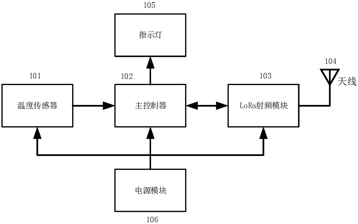
[0029] Such as figure 1 As shown, a LoRa-based bus temperature acquisition device is composed of a temperature sensor 101 , a main controller 102 , a LoRa radio frequency module 103 , an antenna 104 , an indicator light 105 , and a power supply module 106 . Wherein the main controller 102 is connected with the LoRa radio frequency module 103 in two-way communication.

[0030] The temperature sensor 101 is responsible for transmitting the temperature information of the bus duct joint position to the main controller 102, and the main controller 102 processes the information sent by the temperature sensor 101, then transmits it to the LoRa radio frequency module 103, and sends it out through the antenna 104. When the main controller 102 processes the information sent by the temperature sensor 101 and finds that the temperature exceeds the preset threshold value, it will control the indicator light 105 to give an alarm. The power supply module 106 is responsible for supplying pow...

Embodiment 2

[0040] The bus duct temperature acquisition device based on the LoRa Internet of Things and Contiki system has a cloud server (not shown in the figure), which is used to receive and process temperature signals, wherein, the cloud server is provided with a temperature comparison module, which uses To store the temperature threshold value, and compare the detected temperature signal with the temperature threshold value, judge the degree of temperature exceeding, and generate a feedback signal. The difference between this embodiment and Embodiment 1 is that the main controller does not compare the detected temperatures, but the cloud server realizes the above functions, and other settings are the same as Embodiment 1.

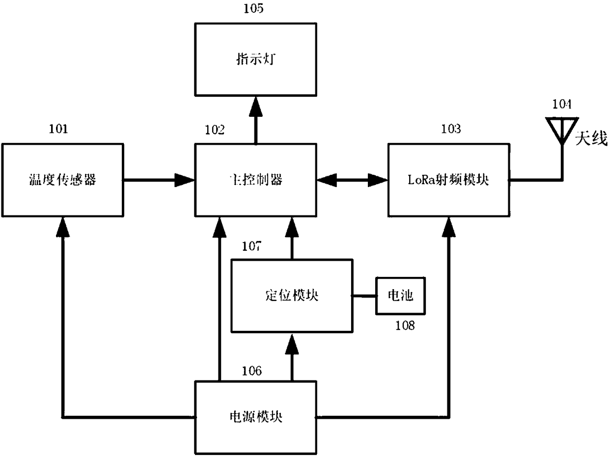
[0041] Certainly also can carry out following deformation setting to present embodiment: described bus duct temperature acquisition device based on LoRa Internet of Things and Contiki system is set to movable portable equipment, can also comprise navigation positio...


PUM


Abstract

The invention discloses an on-line monitoring device, in particular to a bus duct temperature acquisition device based on the LoRa Internet of Things and the Contiki system. The device includes a temperature sensor, a main controller, a LoRa RF module, an antenna, an indicator light, and a power supply module. The temperature collection data transmission adopts the wireless method to reduce the construction complexity and save the construction cost. The problem of distance limitation of the traditional wireless communication methods is solved and the arrangement of the gateway is reduced. Since the gateway cost is generally much higher than the node cost, the construction cost can be greatly reduced.

Description

technical field [0001] The invention relates to an online monitoring device, in particular to a bus duct temperature acquisition device based on the LoRa Internet of Things and Contiki system. Background technique [0002] The busway is a closed metal device composed of copper and aluminum busbar columns, which is used to distribute large power to various components of the decentralized system. It has increasingly replaced wires and cables in indoor low-voltage power transmission trunk line projects. [0003] With the rapid development of our country's economy, the power consumption of all walks of life is increasing day by day, and the traditional cables with a current of thousands of amps seem to be unable to do what they want. At this time, it is a matter of course for the busway to enter the historical stage. [0004] Due to the strong current-carrying capacity of the busway, it is very common to have a current of thousands of A in some occasions with large load power. ...

Claims


Application Information

Patent Timeline
IPC IPC(8): G01K1/02G01K7/02G01K7/22H04L29/08G08C17/02G01K1/024
CPCH04L67/12G08C17/02G01K1/024G01K7/02G01K7/22
Inventor 吴泽雄
Owner 广州莲雾科技有限公司
Why Eureka
Try Eureka