Three-dimensional fin heat exchange plate machining process
A processing technology and heat exchange plate technology, which is applied in the field of three-dimensional fin heat exchange plate processing technology, can solve the problems that it is difficult to meet the three-dimensional fin heat exchange plate, rough flat plate ribbed wall products, and reduced heat transfer efficiency of rib walls. Achieve the effects of reduced volume, improved heat transfer coefficient, and fast processing speed
- Summary
- Abstract
- Description
- Claims
- Application Information
AI Technical Summary
Problems solved by technology
Method used
Image
Examples
Embodiment 1
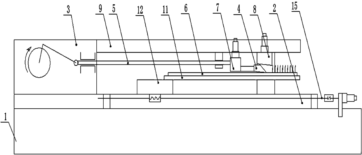
[0053] The cutting equipment of the three-dimensional finned heat exchange plate is described as follows.
[0054] Three-dimensional finned heat exchange plate cutting equipment, such as Figure 1 to Figure 6 As shown, it includes the main body of the machine tool mainly composed of the bed 1, the bed guide rail 2 and the bed head box 3 arranged on the bed guide rail 2. The bed head box 3 is driven by the main motor and the reduction box. A drive mechanism and a crank link mechanism connected to the output end of the drive mechanism are provided. One end of the crank link mechanism is connected to the drive mechanism, and the other end is connected to the input end of the cutter bar 5. The drive mechanism and the crank link mechanism jointly push the cutter bar 5 in a horizontal position. Do reciprocating motion in the direction; a cutter 4 is provided at the output end of the cutter bar 5, and a feed mechanism 8 is arranged on the cutter 4. The cutter tooth 403 of the cutter ...
Embodiment 2
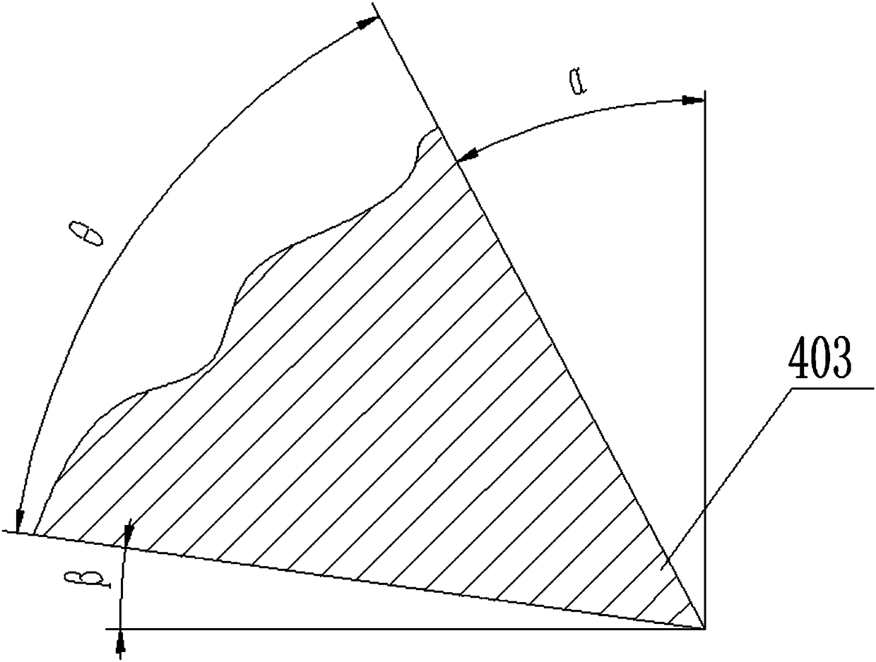
[0070]With reference to embodiment 1, select the cutting tool of cutter tooth 403 wedge angle θ=63 ° for use, its machining process is: first workpiece 6 is fixed on the first supporting plate 11, confirms that the lower surface of workpiece 6 and the upper surface of first supporting plate 11 Start the vacuum pump after the surface fits well, open the vacuum switch to make the vacuum chamber 13 form a vacuum, check the vacuum degree of the vacuum gauge, and check the stability and reliability of the workpiece 6 and the first supporting plate 11; The tool 4 is at the retraction limit; adjust the position of the tool feed mechanism 8 so that the tool 4 completely withdraws from the slope of the inclined block 804; adjust the parallelism between the chisel edge line of the cutter tooth 403 and the upper surface of the workpiece 6, and check with a feeler gauge, the error ≤0.03mm; if image 3 and Figure 6 As shown, the angle of the cutter tooth 403 is adjusted so that an includ...
Embodiment 3
[0072] With reference to embodiment 1, select the cutting tool of cutter tooth 403 wedge angle θ=57 ° for use, its machining process is: first workpiece 6 is fixed on the first supporting plate 11, confirms that the lower surface of workpiece 6 and the upper surface of first supporting plate 11 Start the vacuum pump after the surface fits well, open the vacuum switch to make the vacuum chamber 13 form a vacuum, check the vacuum degree of the vacuum gauge, and check the stability and reliability of the workpiece 6 and the first supporting plate 11; The tool 4 is at the retraction limit; adjust the position of the tool feed mechanism 8 so that the tool 4 completely withdraws from the slope of the inclined block 804; adjust the parallelism between the chisel edge line of the cutter tooth 403 and the upper surface of the workpiece 6, and check with a feeler gauge, the error ≤0.03mm; if image 3 and Figure 6 As shown, adjust the angle of cutter tooth 403, make the included angle ...
PUM
| Property | Measurement | Unit |
|---|---|---|
| thickness | aaaaa | aaaaa |
| width | aaaaa | aaaaa |
Abstract
Description
Claims
Application Information
 - R&D
- Intellectual Property
- Life Sciences
- Materials
- Tech Scout
- Unparalleled Data Quality
- Higher Quality Content
- 60% Fewer Hallucinations
Browse by: Latest US Patents, China's latest patents, Technical Efficacy Thesaurus, Application Domain, Technology Topic, Popular Technical Reports.
© 2025 PatSnap. All rights reserved.Legal|Privacy policy|Modern Slavery Act Transparency Statement|Sitemap|About US| Contact US: help@patsnap.com


