
Coating chamber organic waste gas catalytic combustion treatment system

A technology of catalytic combustion and organic waste gas, which is applied in the field of waste gas treatment system of painting room, can solve the problems of easy blockage of spray paint waste gas and inability of waste gas to reach the standard stably, and achieve the effect of superior thermodynamic performance, significant energy saving effect, and improvement of purification efficiency.

Inactive Publication Date: 2018-06-19
JIANGSU YONGYI ENVIRONMENTAL PROTECTION TECH CO LTD
View PDF11 Cites 8 Cited by
  • Summary
  • Abstract
  • Description
  • Claims
  • Application Information

AI Technical Summary

Problems solved by technology

[0009] Aiming at the problems existing in the prior art, the present invention provides a catalytic combustion treatment system for organic waste gas in the painting room, which solves the problems that the waste gas from spray painting is easy to block and the waste gas cannot meet the standard stably, and the system has a high degree of automation and intelligence, and the waste gas The treatment effect is good, the purification efficiency is >98%, the noise is lower than 30dB, and the emission process of gas and noise meets and exceeds the national emission standard; and it can perform catalytic combustion treatment of exhaust gas online to achieve zero emission of exhaust gas

Method used


Image

  • Coating chamber organic waste gas catalytic combustion treatment system
  • Coating chamber organic waste gas catalytic combustion treatment system
  • Coating chamber organic waste gas catalytic combustion treatment system

Examples


Embodiment

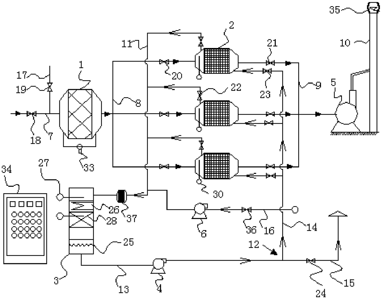
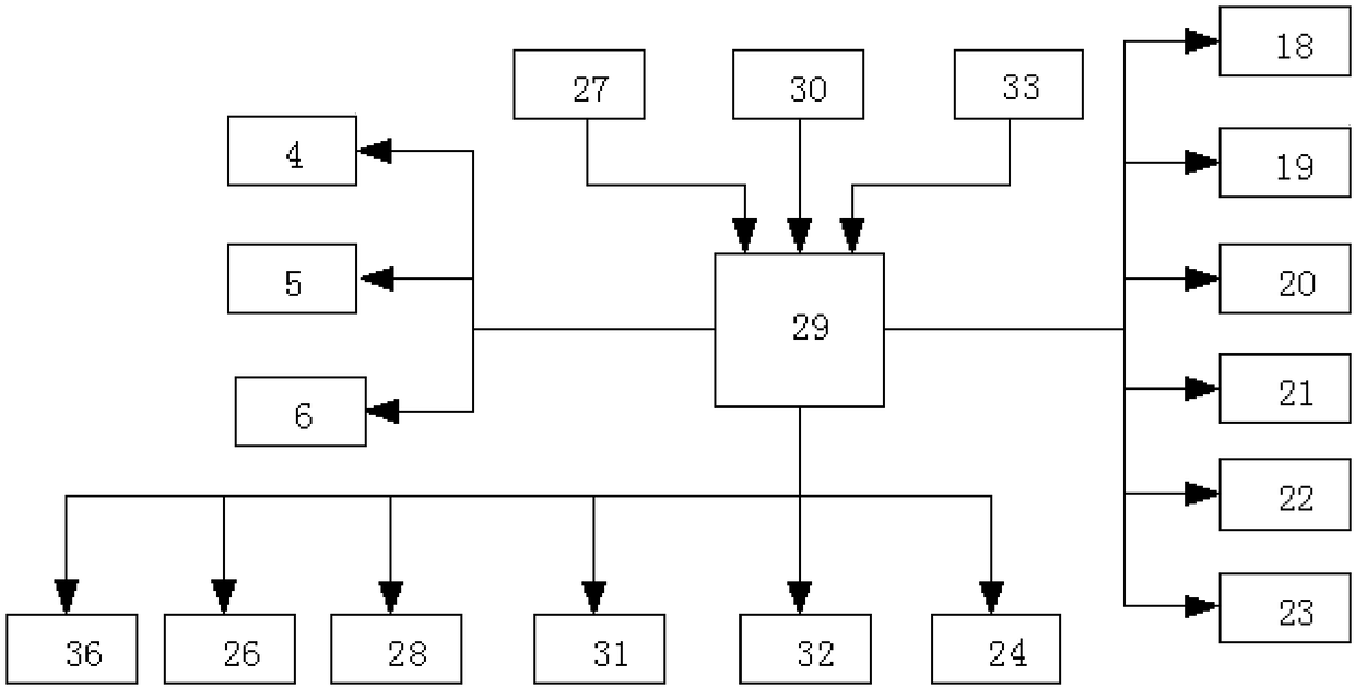
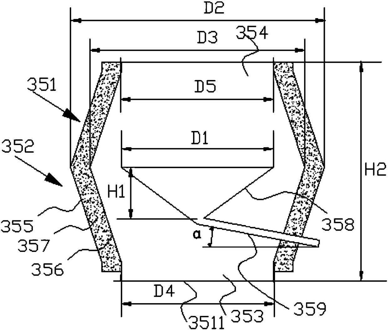
[0043] Example: A catalytic combustion treatment system for organic waste gas in a painting room, such as Figure 1 to Figure 4 As shown, it includes a dry filter 1, an adsorption-desorption box 2, a catalytic combustion device 3, an adsorption fan 5, a desorption fan 4 and an air supply fan 6. The adsorption-desorption box is provided with three, each of the adsorption The desorption boxes all have an adsorption air inlet, an adsorption air outlet, a desorption air inlet and a desorption air outlet, the air inlet of the dry filter is connected to the waste gas collection pipeline 7, and the air outlet of the dry filter is The adsorption air inlet of the adsorption desorption box is connected through the adsorption air intake pipeline 8, the adsorption air outlet of the adsorption desorption box is connected with the adsorption fan through the adsorption air outlet pipeline 9, and the air outlet of the adsorption fan is connected with the exhaust chimney 10 The desorption gas ...


PUM

PropertyMeasurementUnit
Thicknessaaaaaaaaaa
Thicknessaaaaaaaaaa
Heightaaaaaaaaaa

Abstract

The invention discloses a coating chamber organic waste gas catalytic combustion treatment system, which comprises a dry filter, adsorption desorption boxes, a catalytic combustion device, an adsorption fan, a desorption fan and an air supplement fan, and the number of the adsorption desorption boxes is three. The catalytic combustion device is provided with a preheating chamber, a catalytic bed,a heat exchanger and a first thermocouple, and also includes a PLC control system. The PLC control system includes a PLC controller, a first thermocouple and a first over temperature alarm which are installed in the adsorption desorption box, a second over temperature alarm installed on the catalytic combustion device, and a differential pressure gauge arranged on the dry filter. The coating chamber organic waste gas catalytic combustion treatment system solves the problem that paint spraying exhaust gas is easy to block and the exhaust gas cannot stably reach standards, and the system has high automation and intelligence, the treatment effect on the exhaust gas is good, the purification efficiency is greater than 98%, the noise is lower than 30 dB, meets and exceeds the national emissionstandard; and the coating chamber organic waste gas catalytic combustion treatment system can be used for on-line catalytic combustion treatment of the exhaust gas and can achieve zero emissions of the exhaust gas.

Description

technical field [0001] The invention relates to the technical field of exhaust gas treatment, in particular to an exhaust gas treatment system for a painting room. Background technique [0002] The main components of spray paint exhaust gas are paint spray dust and volatilized benzene, toluene, xylene, etc. Random discharge will have a certain impact on the surrounding environment. Therefore, it needs to be discharged after certain treatment. [0003] The traditional treatment process mainly includes: paint exhaust gas→water spray tower→dry-wet separation→primary effect filter→activated carbon adsorption→discharge. [0004] Due to the viscosity of the paint powder, activated carbon adsorption is used to treat organic waste gas. After the activated carbon is saturated, catalytic combustion is used to desorb it. The exhaust gas discharged from the painting room contains a certain amount of paint mist, which is a viscous substance. Therefore, before the exhaust gas enters the a...

Claims


Application Information

Patent Timeline
IPC IPC(8): B01D53/86B01D53/44B01D46/52B01D46/30F23G7/07
CPCB01D46/30B01D46/525B01D53/04B01D53/8687F23G7/07F23G2208/10F23G2209/14F23G2202/60F23G2201/60B01D2253/102B01D2259/40083B01D2258/0258
Inventor 蒋伟
Owner JIANGSU YONGYI ENVIRONMENTAL PROTECTION TECH CO LTD
Learn More