
Polarization parameter measuring device based on carrier frequency orthogonal transmission point diffraction digital holography and measuring method thereof

A technology of digital holography and measuring devices, applied in measuring devices, optical radiation measurement, and measuring the polarization of light, can solve problems affecting the measurement accuracy of polarization state parameters, limited spectrum space separation, and increased system complexity, etc., to achieve system positioning Low complexity requirements, avoiding crosstalk between spectrums, and compact structure

Inactive Publication Date: 2018-06-19
HARBIN ENG UNIV
View PDF8 Cites 0 Cited by
  • Summary
  • Abstract
  • Description
  • Claims
  • Application Information

AI Technical Summary

Problems solved by technology

However, this method requires two-dimensional grating and hole array matching, supplemented by two polarizers with orthogonal polarization, which is not only complex in structure, but also difficult to adjust
[0005] Patent CN 104198040 B "A Holographic Measurement Method and Implementing Device for Two-dimensional Jones Matrix Parameters" utilizes dual two-dimensional grating spectroscopic technology combined with spectrum multiplexing technology to realize Jones matrix parameter measurement through one exposure, but the device not only further increases The complexity of the system is increased, and the light utilization rate is high. At the same time, due to the use of a separate optical path structure, the anti-interference ability is poor
Yuan Caojin from Nanjing Normal University et al. (Ma Jun, Yuan Caojin, Feng Shaotong, Nie Shouping, "Full Field Polarization Measurement Method Based on Digital Holography and Multiplexing Technology", Acta Phys. 22, 224204 (2013)) used polarization and Angle division multiplexing technology can realize Stokes matrix parameter and Jones vector measurement through one exposure, but because of the use of a separate optical path structure, the anti-interference ability is poor; at the same time, due to the structural limitation, the polarization orthogonal spectrum is limited in the spectrum space, and then Cause crosstalk and affect the measurement accuracy of polarization state parameters

Method used


Image

  • Polarization parameter measuring device based on carrier frequency orthogonal transmission point diffraction digital holography and measuring method thereof
  • Polarization parameter measuring device based on carrier frequency orthogonal transmission point diffraction digital holography and measuring method thereof
  • Polarization parameter measuring device based on carrier frequency orthogonal transmission point diffraction digital holography and measuring method thereof

Examples


Embodiment approach 1

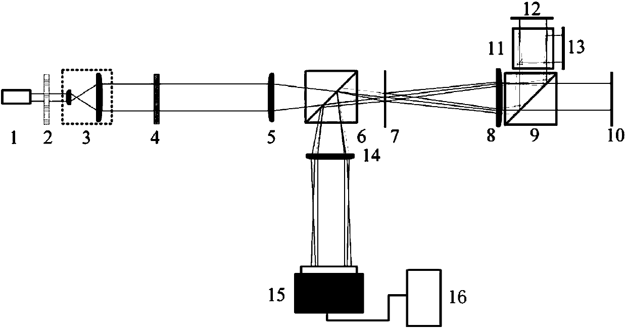
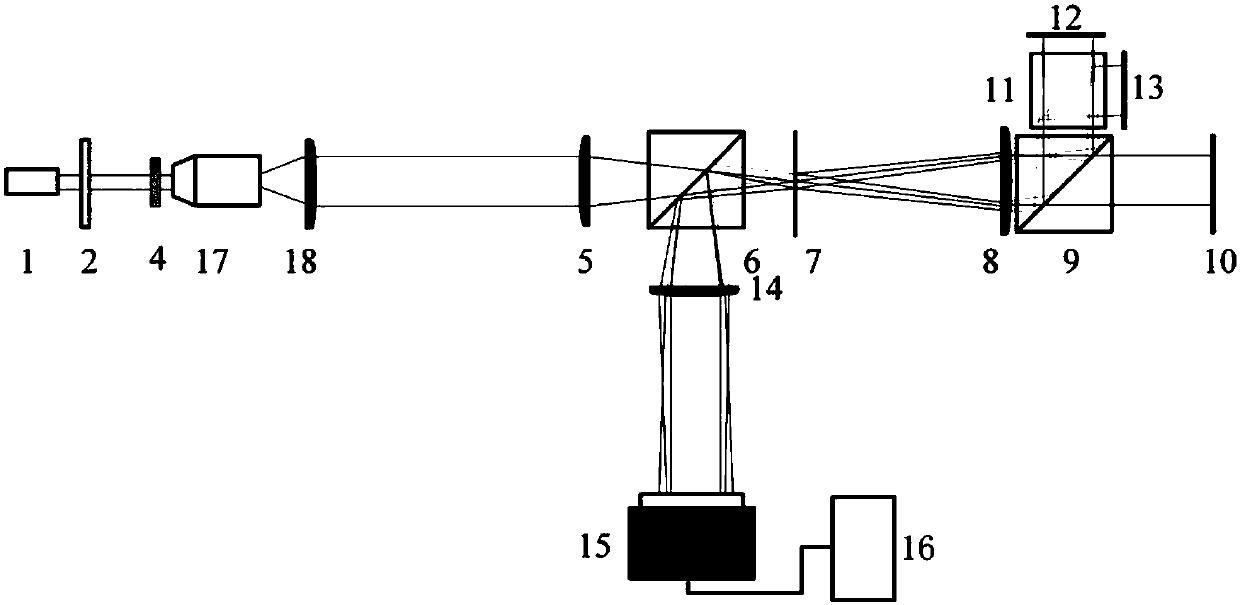
[0035] Implementation mode one: if figure 1 As shown, a polarization state parameter measurement device based on carrier-frequency orthogonal transmission point diffraction digital holography includes a light source with a wavelength of λ, a 45° linear polarization modulation system, and a collimated beam expander system. The device also includes a first lens, A first non-polarizing beam splitter, an aperture array, a second lens, a second non-polarizing beam splitting prism, a first plane mirror, a polarizing beam splitter, a second plane mirror, a third plane mirror, a third lens, an image sensor and Computer; the light beam emitted by the light source is modulated by a 45° linear polarization modulation system to form a linearly polarized light beam. After being collimated and expanded by the collimation beam expansion system, it passes through the object to be measured, the first lens, and the first non-polarizing beam splitter in turn. , the hole array, the second lens, a...

Embodiment approach 2

[0036] Embodiment 2: On the basis of Embodiment 1, the first plane reflector is placed vertically to the optical axis, and the second plane reflector is at an angle θ to the optical axis in the horizontal direction. a angle placement, θ a The angle does not include 90°, the third plane reflector is at the angle θ with the optical axis in the vertical direction b angle placement, θ b Angles do not include 90°.

Embodiment approach 3

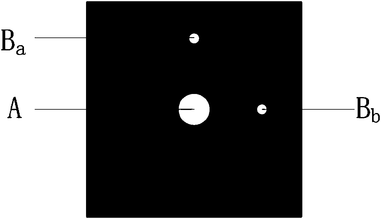
[0037] Embodiment 3: On the basis of Embodiment 1 or 2, the pinhole B on the hole array a Matches the light spot reflected by the third plane mirror and focused by the second lens, pinhole B b The light spot is matched with the light spot reflected by the second plane reflector and focused by the second lens.

[0038] Based on Embodiment 1, 2 or 3, a measurement method of a polarization state parameter measurement device based on carrier frequency orthogonal transmission point diffraction digital holography, the implementation process is as follows:

[0039] (1) Adjust the entire optical system, turn on the light source, and the emitted beam with a wavelength of λ is modulated by a 45° linear polarization modulation system to form a linearly polarized beam. After being collimated and expanded by the collimator beam expander system, it passes through the object to be measured and the first lens to form a focused beam, and then pass through the first non-polarizing beam splitte...


PUM


Abstract

The invention relates to a polarization parameter measuring device based on carrier frequency orthogonal transmission point diffraction digital holography and a measuring method thereof. The 45-degreelinearly polarized light beam passes through an object to be measured, a first lens, a first non-polarized light splitting prism, a hole array, a second lens and a second non-polarized light splitting prism to form object light and reference light; the object light irradiates a first plane mirror to be reflected to the second non-polarized light splitting prism, and the reference light is dividedinto two beams of light through the polarized light splitting prism to irradiate a second plane mirror and a third plane mirror to be reflected and then irradiate the second non-polarized light splitting prism through the polarized light splitting prism; and the object light and the reference light converged to the second non-polarized light splitting prism pass through the second lens, the holearray, the first non-polarized light splitting prism and a third lens in turn to form a carrier frequency orthogonal hologram including the polarization component information to be acquired by an image sensor to a computer to compute the Stokes matrix parameter and the Jones matrix parameter.

Description

technical field [0001] The invention belongs to the field of polarization state parameter measurement, in particular to a polarization state parameter measurement device and method based on carrier frequency orthogonal transmission point diffraction digital holography. Background technique [0002] Polarization state is one of the important parameters to describe the wavefront characteristics of light waves. It can be characterized by Stokes matrix parameters and Jones matrix parameters. Its measurement has important scientific significance and significance in the fields of biophotonics, nonlinear optics, chemistry and mineralogy Value. However, the traditional polarization state measurement device can only provide polarization information at a fixed position in the propagation direction of the wavefront to be measured, and because it does not have two-dimensional sampling characteristics, frequent adjustment of the optical path and multiple exposures are required to achieve...

Claims


Application Information

Patent Timeline
Patent Type & Authority Applications(China)
IPC IPC(8): G01J4/00
CPCG01J4/00G01J4/04
Inventor 单明广刘磊钟志刘彬张雅彬
Owner HARBIN ENG UNIV
Learn More