Urea-solution pyrolysis system for flue-gas denitrification

A technology of solution heat and urea, which is applied in the field of energy saving and emission reduction, can solve the problems of pipeline equipment blockage, short urea pyrolysis time, and blocked pipelines, so as to reduce the blockage and damage of pipeline equipment, increase the unit reaction area, avoid blockage and damage effect

Pending Publication Date: 2018-06-29
CHINA HUADIAN ENG +1
View PDF5 Cites 6 Cited by
  • Summary
  • Abstract
  • Description
  • Claims
  • Application Information

AI Technical Summary

Problems solved by technology

The sources of ammonia used in the denitrification reaction include liquid ammonia, ammonia water and urea. Among them, liquid ammonia and ammonia water are explosive and highly toxic, and are prone to accidents during transportation and storage. Urea is a common agricultural Fertilizer, transportation and storage are relatively safe. Therefore, ammonia gas is usually produced by urea hydrolysis and pyrolysis. The acidic substances produced in the process of hydrolyzing urea to ammonia are very easy to corrode pipeline equipment, causing blockage of pipeline equipment and However, the use of urea pyrolysis to produce ammonia is relatively safe and mild, so it is more common to use urea pyrolysis to produce ammonia. However, the existing urea pyrolysis system has a complex structure and high operating costs. Reasons such as short time, insufficient reaction temperature, etc., all easily lead to incomplete pyrolysis. On the one hand, the prepared ammonia gas is not enough to remove nitrogen oxides in the flue gas through reaction. On the other hand, incomplete pyrolysis of urea forms crystals to block pipes and equipment.

Method used


Image

  • Urea-solution pyrolysis system for flue-gas denitrification
  • Urea-solution pyrolysis system for flue-gas denitrification

Examples


Embodiment 1

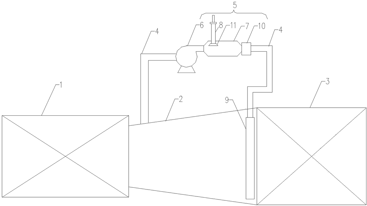
[0021] Embodiment 1 of the present invention: a kind of flue gas denitrification urea solution pyrolysis system, such as figure 1 As shown, it includes a gas turbine 1, a connecting flue 2, a waste heat boiler 3, an outlet flue 4 and a urea pyrolysis device 5, the gas turbine 1 and the waste heat boiler 3 are connected through a connecting flue 2, and the connecting flue 2 Both ends are externally connected with a lead-out flue 4, and the said lead-out flue 4 is provided with a urea pyrolysis device 5, wherein the urea pyrolysis device 5 includes a high-temperature blower fan 6, a diameter-expanding flue 7 and a urea spray gun 8, and the high-temperature The blower fan 6 is connected with the diameter-expanding flue 7, and the high-temperature fan 6 and the diameter-expanding flue 7 are arranged on the outlet flue 4, and the expanding-diameter flue 7 is also provided with a urea spray gun 8, in order to make the urea spray gun 8 The urea solution sprayed in can be more fully p...

Embodiment 2

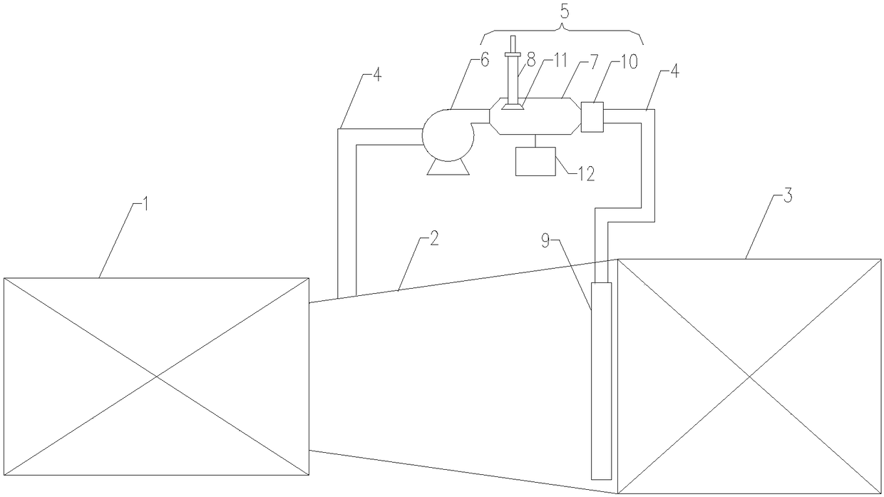
[0022] Embodiment 2: A kind of flue gas denitrification urea solution pyrolysis system, such as figure 2 As shown, it includes a gas turbine 1, a connecting flue 2, a waste heat boiler 3, an outlet flue 4 and a urea pyrolysis device 5, the gas turbine 1 and the waste heat boiler 3 are connected through a connecting flue 2, and the connecting flue 2 Both ends are externally connected with a lead-out flue 4, and the said lead-out flue 4 is provided with a urea pyrolysis device 5, wherein the urea pyrolysis device 5 includes a high-temperature blower fan 6, a diameter-expanding flue 7 and a urea spray gun 8, and the high-temperature The blower fan 6 is connected with the diameter-expanding flue 7, and the high-temperature fan 6 and the diameter-expanding flue 7 are arranged on the outlet flue 4, and the expanding-diameter flue 7 is also provided with a urea spray gun 8, in order to make the urea spray gun 8 The urea solution sprayed in can be more fully pyrolyzed to obtain ammon...


PUM


Abstract

The invention relates to the technical field of energy conservation and emission reduction and particularly relates to an urea-solution pyrolysis system for flue-gas denitrification. The urea-solutionpyrolysis system comprises a flue-gas turbine (1), a connecting flue (2), a waste-heat boiler (3), leading-out flues (4) and an urea pyrolysis device (5), wherein the flue-gas turbine (1) is connected with the waste-heat boiler (3) by the connecting flue (2); the two ends of the connecting flue (2) are externally connected with the leading-out flues (4); the urea pyrolysis device (5) is arrangedon one leading-out flue (4). The urea-solution pyrolysis system has the beneficial effects that the structure is simple, the operating cost is low, the heat needed for urea pyrolysis reaction can be provided by effectively utilizing flue gas, suitable urea-pyrolysis reaction temperature and fuller urea pyrolysis are ensured, so that the risk of blockage and damage of pipeline equipment caused by crystal due to incomplete urea pyrolysis is reduced, ammonia gas obtained by urea pyrolysis can react with nitrogen oxides more fully, and the energy-conserving and emission-reducing effects and the pollution-free and environment-friendly effects are achieved.

Description

technical field [0001] The invention relates to the technical field of energy saving and emission reduction, in particular to a urea solution pyrolysis system for flue gas denitrification. Background technique [0002] Nitrogen oxides are currently one of the most important air pollutants and the main factor causing acid rain, which is particularly harmful to the natural environment. The boiler flue gas of thermal power plants and other manufacturers contains a large amount of nitrogen oxides. In response to the national call for energy conservation and emission reduction, many manufacturers including thermal power plants have strictly controlled the emission of nitrogen oxides, and mainly The nitrogen oxides in the boiler flue gas are removed by denitration reaction. The principle of denitration reaction is to use the reducing agent ammonia (NH 3 ) to reduce the nitrogen oxides in the flue gas to nitrogen and water. The sources of ammonia used in the denitrification react...

Claims


Application Information

Patent Timeline
Patent Type & Authority Applications(China)
IPC IPC(8): B01D53/56B01D53/76C01C1/08
CPCB01D53/56B01D53/76C01C1/086B01D2251/2062Y02P20/129Y02P20/10
Inventor 刘晓立张起王凯亮吴冲安亚利
Owner CHINA HUADIAN ENG
Why Eureka
Try Eureka