Temperature-control hot-gas bypass automatic-backflow continuous-defrosting plate ice heat pump

A hot gas bypass and automatic return technology, applied in heat pumps, fluid circulation arrangements, lighting and heating equipment, etc., can solve the problem of affecting the deicing performance of the evaporator, increasing the configuration cost and energy consumption, and reducing the heating capacity of the unit Improve ice-making heating capacity and operating efficiency, reduce investment cost and operating cost, and prevent local surface temperature from being too high

Pending Publication Date: 2018-07-10
罗良宜
View PDF0 Cites 2 Cited by
  • Summary
  • Abstract
  • Description
  • Claims
  • Application Information

AI Technical Summary

Problems solved by technology

[0004] Conventional ice machines such as plate ice machines, flake ice machines, and block ice machines can extract 0°C water-ice phase change latent heat for heating and heating by making ice in winter. This large amount of 0°C heat source has nothing to do with the low temperature environment; In summer, the machine can also make ice and store ice during the low-cost off-peak electricity period at night, but the evaporation temperature of the nominal working condition of ice making and heating is below -18°C, which consumes a lot of energy and requires a lot of investment. Regardless of whether it is economical to control ice or heating very bad
Conventional plate ice machines use tube-plate heat exchangers or plate-plate heat exchangers. Tube-plate heat exchangers or plate-plate heat exchangers are made of stainless steel plate brazing or laser welding, which is expensive and has low heat transfer efficiency.
At present, conventional plate ice machines usually use hot fluorine to defrost and de-ice. The ice-making cycle system of the unit operates intermittently, which has low efficiency and has high requirements on the compressor and its refrigeration system. In addition, the evaporation temperature and pressure of ice making are very low, need to use low-temperature impact-resistant compressor and its accessories, and the system configuration cost is too high
There is also an improved hot gas bypass continuous ice-melting and de-icing method. The unit can continuously heat and make ice. There are multiple sets of evaporators. Each set of evaporators takes turns to defrost and de-ice, and the refrigerant in the other evaporators evaporates and absorbs heat normally; The hot gas of the high-temperature and high-pressure refrigerant is directly bypassed from the compressor exhaust port to the evaporator that needs to be defrosted and deiced. The high-temperature and high-pressure gas at the outlet is heat-exchanged and evaporated. During the evaporation process, no ice is produced, and the heat of the gas at the exhaust port of the compressor is consumed, which will reduce the heating capacity of the unit and reduce the ice-making and heating efficiency of the unit.
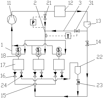
Because the precise control of the expansion valve on the circulating refrigerant flow directly affects the stability, capacity and efficiency of the system, the patent application "A Hot Gas Bypass Pressurized Return Continuous Defrosting Device" provides a hot gas bypass pressurized return continuous melting The ice device ensures the precise control of the expansion valve during the defrosting process, and the cycle stability of the whole unit has been greatly improved, but the temperature of the hot gas at the outlet of the compressor is usually very high, which can exceed 100 ° C, and the superheated gas directly enters the ice-melting evaporator First, it will cause uneven heating and cooling of the evaporator, which will easily cause deformation of the evaporator, which will affect the material selection of the evaporator, the deicing performance and the service life of the evaporator. Second, the high-temperature hot gas directly enters the evaporator, and the local surface temperature of the evaporator High, large temperature difference in local melting ice, fast local heat transfer, large heat consumption, and a large amount of ice melting, which is not conducive to improving ice-making efficiency and heating efficiency
In order to solve the problem that the superheated gas at the outlet of the conventional hot fluorine frosting compressor exceeds 100°C and directly enters the ice-melting evaporator, causing uneven heating and cooling of the evaporator and easily causing deformation of the evaporator, the patent application "An energy-saving dynamic plate ice heat pump" Provide an energy-saving dynamic plate ice heat pump with low cost of ice-making evaporator, high heat transfer efficiency, uniform heating of ice-making evaporator during ice melting and deicing process, continuous and stable main engine circulation system, low unit supporting cost, high-pressure hot gas evaporates during defrosting Condensation and liquefaction in the condenser group, the condensed refrigerant flows into the high-pressure liquid receiver through the return liquid receiver, and the superheated hot gas is mixed with the liquid refrigerant from the outlet of the refrigerant pump through the liquid return valve to control the flow rate, and the liquid refrigerant absorbs heat and evaporates , the temperature of the superheated hot gas decreases to become saturated steam at a lower temperature, avoiding the high temperature superheated hot gas directly entering the evaporator, so that there is no thermal shock to the evaporator, and the deformation of the evaporator is prevented, but the pressure in the defrosting evaporator group is unstable, and the defrosting evaporates The pressure difference between the evaporator group and the high-pressure accumulator changes greatly. To press the liquid refrigerant from the defrosting evaporator into the high-pressure accumulator requires the use of a high-pressure pump, which increases the configuration cost and energy consumption of the pump, and has advantages in large-scale device applications. , higher cost for small and medium-sized devices

Method used


Image

  • Temperature-control hot-gas bypass automatic-backflow continuous-defrosting plate ice heat pump

Examples


Embodiment

[0011] Example: see figure 1 , a temperature-controlled hot gas bypass automatic return continuous defrosting plate ice heat pump, including a heating main circulation system, a hot gas bypass branch 2 and a liquid return branch 3; it also includes conventional supporting components of a refrigeration system connected in the system , pipelines, valves, and detection and control systems; three sets of heat exchangers are connected in parallel, and three three-way valves 18 are used to control switching respectively, and each set of heat exchangers performs heating, ice melting and deicing alternately. When the evaporator group 17 is running in the heating mode, the heating cycle main circuit 1 is conducted, the three-way valve 18 leads to the air inlet of the compressor 11, the ice-making check valve 16 is automatically opened, and the ice-melting check valve 24 The heating cycle main circuit 1 includes the evaporator group 17, the three-way valve 18, the compressor 11, the con...


PUM


Abstract

The invention provides a temperature-control hot-gas bypass automatic-backflow continuous-defrosting plate ice heat pump. The temperature-control hot-gas bypass automatic-backflow continuous-defrosting plate ice heat pump comprises a main heating circulation system, a hot-gas bypass branch and a liquid return branch. A plurality of sets of evaporators are connected in parallel, so that heating, ice melting and de-icing are conducted alternately. Bypass high-pressure hot gas and a liquid refrigerant from a backflow valve are mixed to achieve cooling. The pressure of the bypass branch is controlled by a bypass valve to be constant. The ice melting and de-icing efficiency is extremely high. The liquid refrigerant enters a liquid distributor at a stable flow, so that the influence on the stability of the refrigerant flow, temperature and pressure in the main heating circulation system in operation is extremely small. A unit operates continuously, stably and efficiently. The system structure is simple. The investment cost and the operation cost of the heat pump unit can be effectively reduced.

Description

technical field [0001] The invention relates to the technical field of refrigeration, in particular to a temperature-controlled hot gas bypass automatic return flow continuous defrosting plate ice heat pump. Background technique [0002] Air source heat pumps take into account the advantages of cooling and heating, small space occupation, energy saving, environmental protection, and convenience. An important factor in thermal capacity and operating efficiency, its design conditions must also meet the local extreme low temperature conditions, resulting in high power configuration of air source heat pump units, high overall cost, and low efficiency; currently, the commonly used defrosting method for air source heat pumps is hot gas bypass Defrost and hot gas reverse flow defrost, as well as phase change energy storage defrost, electric heating refrigerant defrost, etc., are all intermittent defrosts. During defrosting, the heating function of the unit stops and resumes after d...

Claims


Application Information

Patent Timeline
Patent Type & Authority Applications(China)
IPC IPC(8): F25B30/02F25B41/04F25B41/06F25B49/02F25B41/20F25B41/31
CPCF25B30/02F25B49/02F25B41/20F25B41/31
Inventor 罗良宜
Owner 罗良宜
Why Eureka
Try Eureka