An anoxic fluidized bed device for treating industrial wastewater

A technology of industrial wastewater and fluidized bed, applied in anaerobic digestion treatment, biological water/sewage treatment, water/sludge/sewage treatment, etc. In order to improve the biological reaction efficiency, optimize the water distribution method, reduce the damage of the circulating pump and the possibility of blocking the circulating pipeline

Active Publication Date: 2021-07-30
CHINA PETROLEUM & CHEM CORP +1
View PDF7 Cites 0 Cited by
  • Summary
  • Abstract
  • Description
  • Claims
  • Application Information

AI Technical Summary

Problems solved by technology

[0006] First of all, the water inlet pressure of the downward flow reactor is relatively high, which not only greatly increases the operating cost, but also is not conducive to operation and maintenance;
[0007] Secondly, the water distribution system of the conventional upflow anoxic denitrification fluidized bed treatment device needs to be cleaned frequently to keep it smooth, especially when the reactor is overloaded, the phenomenon of filter material blockage is very likely to occur, which affects the distribution of influent water and The effect of wastewater treatment will have adverse effects;
[0008] Third, the anoxic fluidized bed needs to be backwashed regularly to remove the thicker biofilm attached to the surface of the filler. During the combined air-water backwash process, a large number of small and light fillers will flow into the circulation pipeline, causing Pipeline blockage or even damage to the pump head will seriously affect the long-term stable operation of the reactor

Method used


Image

  • An anoxic fluidized bed device for treating industrial wastewater
  • An anoxic fluidized bed device for treating industrial wastewater
  • An anoxic fluidized bed device for treating industrial wastewater

Examples


Embodiment Construction

[0062] The present invention will be described in further detail below in conjunction with the accompanying drawings.

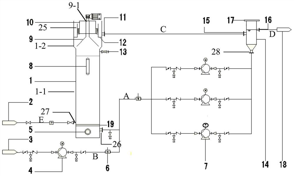
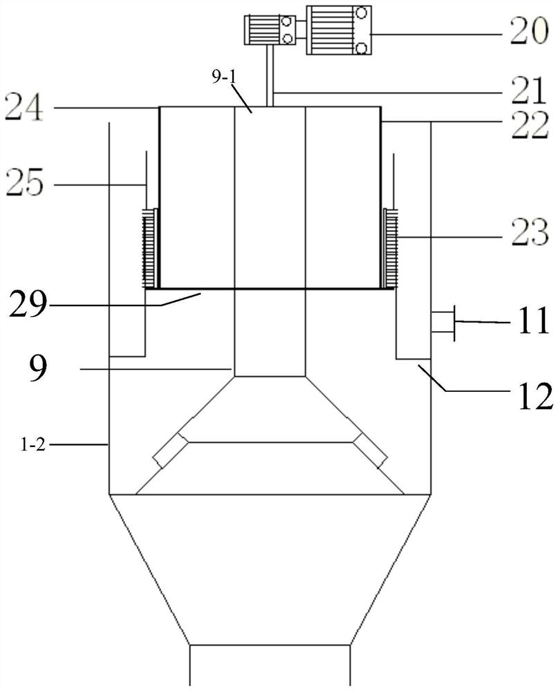
[0063] Such as figure 1 Shown in -3, the anoxic fluidized bed device for industrial waste water treatment of the present invention is a full-automatic high-efficiency organic wastewater treatment device composed of anoxic fluidized bed and self-cleaning filter etc., specifically as follows:

[0064] An anoxic fluidized bed device for treating industrial wastewater, comprising:

[0065] The main body 1 of the anoxic fluidized bed device includes a tower body 1-1 and a tower head 1-2;

[0066] The tower body 1-1 is a hollow cylinder, and the tower head 1-2 is located at the upper part of the tower body 1-1 and is a hollow cylinder with a diameter larger than the tower body 1-1;

[0067] An anoxic fluidized bed water inlet 26 is arranged on the lower side wall of the tower body 1-1,

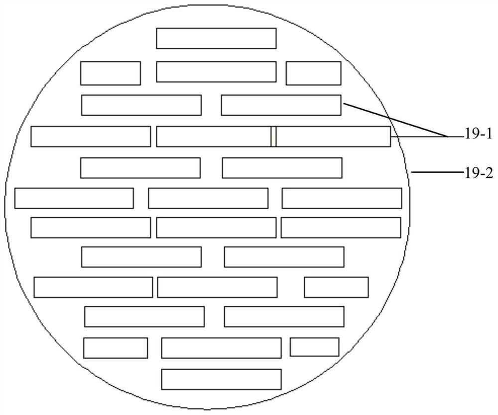
[0068] In the tower body 1-1, a water flow distributor 19 is arranged above...


PUM

PropertyMeasurementUnit
diameteraaaaaaaaaa
diameteraaaaaaaaaa

Abstract

The invention relates to an anoxic fluidized bed device for treating industrial waste water. The device comprises an anoxic fluidized bed device main body (1), and a self-cleaning filter device (10) is established in the tower head (1-2) of the anoxic fluidized bed device main body (1), wherein the filter screen (25) The mesh diameter is slightly smaller than the diameter of the biological filler, which effectively prevents the biological filler in the main body (1) of the anoxic fluidized bed device from being discharged out of the circulation system, and the relative movement between the metal brush (23) and the filter screen (25) makes The sludge originally attached to the filter screen (25) is broken up and stripped to achieve the purpose of cleaning the filter screen (25), so that the long-term stable operation of the circulation system; the main body (1) of the anoxic fluidized bed device (1- 1) The water flow distributor (19) at the inner bottom effectively solves the problem of uneven water distribution in the main body (1) of the anoxic fluidized bed device, avoids short circuit of water flow, and increases the removal load of organic matter and nitrate.

Description

technical field [0001] The invention relates to the technical fields of chemical industry and environmental protection, in particular to an anoxic fluidized bed device for treating industrial waste water. Background technique [0002] In recent years, nitrogen pollution in the field of water treatment has become one of the social hot spots. With the increasingly serious problem of eutrophication in China's water bodies and the improvement of future wastewater discharge standards, the removal of nitrogen in water has become one of the key issues in the field of water treatment. How to remove nitrate nitrogen from water economically, efficiently and safely, and develop an efficient and stable wastewater enhanced denitrification technology has become an urgent technical demand in the field of wastewater treatment. [0003] Today's wastewater treatment is faced with high standard discharge requirements, such as the United States, Canada and other countries, the effluent standar...

Claims


Application Information

Patent Timeline
Patent Type & Authority Patents(China)
IPC IPC(8): C02F3/28
CPCC02F3/2833
Inventor 程学文张宾王珺莫馗高凤霞李海龙侯秀华
Owner CHINA PETROLEUM & CHEM CORP
Why Eureka
Try Eureka