
Far infrared heating electronic cigarette module

A far-infrared ray and electronic cigarette technology, applied in the field of electronic cigarette technology, can solve the problems of uneven heating, poor fiber rope liquid conduction performance, poor atomization effect, etc., achieve rapid and uniform heating, increase atomization rate, and avoid carbonization problems Effect

Pending Publication Date: 2018-08-10
杭州森翼科技有限公司
View PDF2 Cites 10 Cited by
  • Summary
  • Abstract
  • Description
  • Claims
  • Application Information

AI Technical Summary

Problems solved by technology

However, it has the hidden danger of easy coking on the surface of the glass fiber rope; at the same time, due to the poor liquid conduction performance of the fiber rope, there are problems such as unsatisfactory e-liquid penetration speed, easy carbonization, and poor atomization effect during continuous smoking; in addition, the electronic cigarette heating wire When heating the e-liquid adsorbate from the middle, there is a phenomenon of uneven heating, which affects the quality of the e-cigarette
[0003] Patent CN203952443 U discloses an ordinary porous ceramic instead of a fiber rope as an atomization component of an electronic cigarette. Patent CN104161308A applies for a method of using hollow microporous ceramics as an atomization unit of an electronic cigarette. In order to increase the atomization speed of e-liquid , Generally, it is necessary to use a heating wire with a high resistance value. Although the ceramic core can improve the burning problem of the smoke oil, the ceramic chip is easy to break during the assembly process.
For low-temperature non-burning e-cigarettes using ceramic heating rods, there is a problem of uneven heating of e-liquid adsorbents, which leads to changes in the taste of e-cigarettes before and after use

Method used


Image

  • Far infrared heating electronic cigarette module

Examples


Embodiment 1

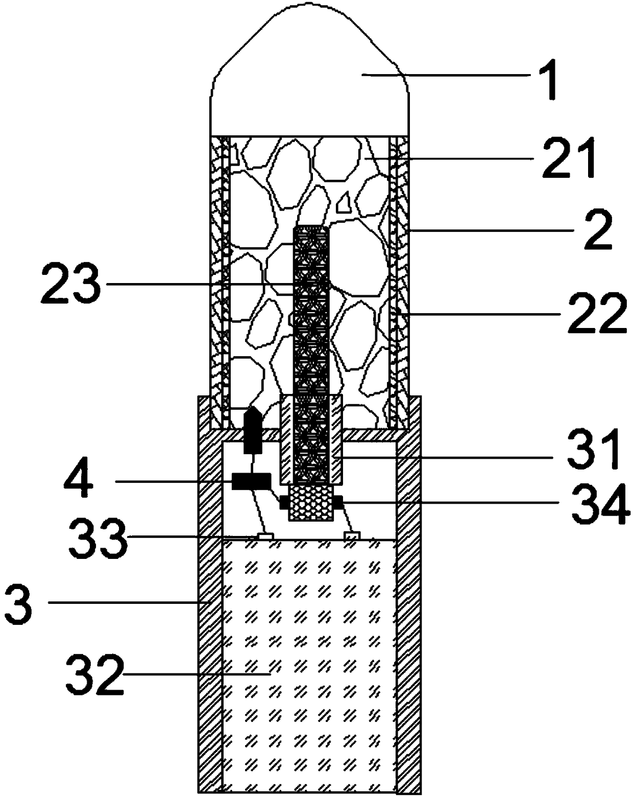
[0028] Such as figure 1 As shown, an electronic cigarette module that uses far-infrared heating includes a mouthpiece 1, an atomizer 2, a base 3, a far-infrared heating body 23, and a transistor controller 4. The atomizer 2 is a hollow cylinder inside The far-infrared heating body is composed of a cylindrical silicon carbide ceramic layer with a diameter of 0.5cm, and its length is 4 / 5 of the length of the atomizer 2; the bottom of the atomizer 2 is open, the top of the base 3 has a cutout, and the mouthpiece 1 is set on the top of the atomizer 2, the atomizer 2 is installed on the base 3, the inside of the atomizer 2 is filled with expanded graphite 21, the inner wall of the atomizer 2 is provided with a far-infrared reflective layer 22, and the inside of the base 3 The battery 32 is installed, the top of the far-infrared heating body 23 extends into the inside of the atomizer 2, and the bottom extends into the inside of the base 3 through a cutout. The valve tube controller...

Embodiment 2

[0033] Such as figure 1 As shown, an electronic cigarette module that uses far-infrared heating includes a mouthpiece 1, an atomizer 2, a base 3, a far-infrared heating body 23, and a transistor controller 4. The atomizer 2 is a hollow cylinder inside The far-infrared heating body is composed of a cylindrical rare earth nitride ceramic layer with a diameter of 1.5cm, and its length is 4 / 5 of the length of the atomizer 2; the bottom of the atomizer 2 is open, and the top of the base 3 has a cutout , the mouthpiece 1 is set on the top of the atomizer 2, the atomizer 2 is installed on the base 3, the inside of the atomizer 2 is filled with expanded graphite 21, the inner wall of the atomizer 2 is provided with a far-infrared reflective layer 22, the base 3 is equipped with a battery 32, the top of the far-infrared heating body 23 extends into the inside of the atomizer 2, and the bottom extends into the inside of the base 3 through a cutout. One end is electrically connected to ...

Embodiment 3

[0036] Such as figure 1As shown, an electronic cigarette module that uses far-infrared heating includes a mouthpiece 1, an atomizer 2, a base 3, a far-infrared heating body 23, and a transistor controller 4. The diameter of the far-infrared heating body 23 is 1.5 cm cylindrical and composed of nickel-cobalt oxide ceramics and zirconium-titanium boride ceramic layers from the inside to the outside, and its length is 4 / 5 of the length of the atomizer shell; atomizer 2 has an opening at the bottom and a base 3 There is a cutout on the top, the mouthpiece 1 is set on the top of the atomizer 2, the atomizer 2 is installed on the base 3, the atomizer 2 is filled with expanded graphite 21, and the inner wall of the atomizer is provided with a far-infrared reflective layer 22. A battery 32 is installed in the base 3. The top of the far-infrared heating body 23 extends into the atomizer 2, and the bottom extends into the inside of the base 3 through a cutout. The bottom end of the far-...


PUM


Abstract

The invention provides a far infrared heating electronic cigarette module. The electronic cigarette module comprises a cigarette holder, an atomizer, a base, a far infrared heating body and a temperature regulation and control device, wherein an opening is formed in the bottom of the atomizer; a notch is formed in the top of the base; the cigarette holder is arranged on the top of the atomizer; the atomizer is mounted on the base and is filled with expanded graphite; a battery is mounted in the base; the top of the far infrared heating body extends into the atomizer; the bottom of the far infrared heating body extends into the base through the notch, and is electrically connected with the battery; one end of the temperature regulation and control device is connected with the inside of theatomizer while the other end of the temperature regulation and control device is electrically connected with the battery; and one or two far infrared reflecting layers is arranged on the inner side wall of the atomizer. The far infrared heating body is arranged in the atomizer of the electronic cigarette, far infrared rays generated by radiation can effectively penetrate through tobacco tar or a tobacco tar load, rapid and uniform heating is implemented, and meanwhile, the problem of uneven tobacco tar volatilization due to over-high local temperature can be avoided.

Description

technical field [0001] The invention belongs to the technical field of electronic cigarette technology, and in particular relates to an electronic cigarette module heated by far-infrared rays. Background technique [0002] The heating device of the electronic cigarette vaporizer in the prior art is generally directly wound by a metal heating wire on a glass fiber rope, and the glass fiber rope penetrates into the e-liquid through capillary phenomenon, and an external voltage is applied to the heating wire, and the heating wire generates heat and atomizes the e-liquid . However, it has the hidden danger of easy coking on the surface of the glass fiber rope; at the same time, due to the poor liquid conduction performance of the fiber rope, there are problems such as unsatisfactory e-liquid penetration speed, easy carbonization, and poor atomization effect during continuous smoking; in addition, the electronic cigarette heating wire When the e-liquid adsorbate is heated from t...

Claims


Application Information

Patent Timeline
Patent Type & Authority Applications(China)
IPC IPC(8): A24F47/00
CPCA24F47/008
Inventor 倪健雄
Owner 杭州森翼科技有限公司
Learn More