Inductance element and manufacturing method

A technology of inductive components and electrodes, which is applied in the direction of electrical components, inductance/transformer/magnet manufacturing, transformer/inductance parts, etc., can solve the problem that it is difficult to ensure the position of the coil design, the product space utilization rate is low, and the coil is easy to shift and other issues to achieve good consistency, reduce the risk of open circuits, and high reliability

Pending Publication Date: 2018-08-10
SHENZHEN SUNLORD ELECTRONICS
View PDF5 Cites 23 Cited by
  • Summary
  • Abstract
  • Description
  • Claims
  • Application Information

AI Technical Summary

Problems solved by technology

[0004] For traditional one-piece inductors, the coil is placed in the empty mold cavity first, and then filled with powder for pressing. It is difficult to ensure that the coil can be in the designed position, the coil is easy to shift, and the product space utilization rate is low.

Method used


Image

  • Inductance element and manufacturing method
  • Inductance element and manufacturing method
  • Inductance element and manufacturing method

Examples


example 1

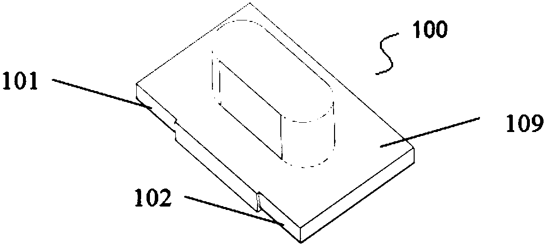
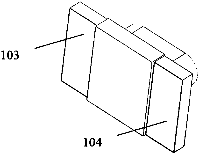
[0061] Such as figure 1 As shown, the T-shaped magnetic core of FeSiCr material can be manufactured by one-time pressing and molding process, preferably, the magnetic permeability is 40-150, and the saturation magnetic flux is 10000-15000 mT. Preferably, as figure 2 As shown, the bottom of the magnetic core is provided with two parallel electrode slots 103, 104, and two wire hanging slots or electrode slots 101, 102 are provided on the side. The metallization layer is preferably formed in the electrode groove by a sputtering process.

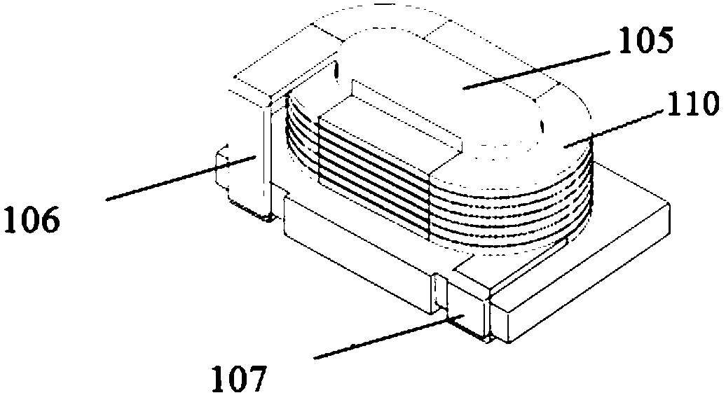
[0062] A winding machine may be used to wind the wires on the central column 105 of the T-shaped magnetic core. Such as image 3 As shown, preferably, after the coil winding product is completed, the lead-out ends 106, 107 of the coil are received into the electrode slots 103, 104.

[0063] Figure 4 It is a schematic diagram of the finished product formed after magnetic glue potting. The magnetic core wrapped with the wire is covered wi...

example 2

[0066] Such as Figure 6 As shown, the metal soft magnetic alloy I-shaped prefabricated magnetic core can also be made by powder molding process. Preferably, the magnetic permeability is 40-90, the saturation magnetic flux is 10000-15000mT, and the material of the I-shaped magnetic core is preferably carbonyl iron powder .

[0067] The base of the prefabricated I-shaped magnetic core can be rectangular, such as Figure 7 As shown, a flat coil can be wound on the center column 203 of the prefabricated magnetic core by a winding machine, which has two lead-out ends 201, 202, and the two lead-out ends 201, 202 are respectively bent and closely attached to the I-shaped magnetic core. The lower blade 204 sides of the core. Then, by laser welding, the metallized layers of the two lead-out ends 201, 202 are welded on the side to form a Figure 7 structure shown.

[0068] Figure 8 It is a schematic diagram of wrapping the flat coil with the magnetic glue layer 205 . Figure 9 ...


PUM

PropertyMeasurementUnit
particle diameteraaaaaaaaaa

Abstract

The invention discloses an inductance element. The inductance element comprises a magnetic core, a flat coil wound on a center pillar of the magnetic core and magnetic plastic package layers with which the magnetic core and the flat coil are coated, wherein two electrodes connected with two leading-out ends of the flat coil are exposed out of the magnetic plastic package layers; the flat coil is configured in such a manner that the width direction of a flat wire of the flat coil is perpendicular to the axial direction of the center pillar of the magnetic core; the flat wire is laminated layerby layer in the axial direction of the center pillar. Moreover, the invention further discloses a manufacturing method of the inductance element. According to the winding mode of the flat coil of theinductance element disclosed by the invention, the height of the product can be reduced under the condition of same DCR, so that the product is thinner.

Description

technical field [0001] The invention relates to an inductance element and a manufacturing method. Background technique [0002] With the rapid development of the Internet, the requirements for IC technology are getting higher and higher. Integration and miniaturization are the trend of historical development. At the same time, the overall requirements for power inductors are miniaturization, thinning, high frequency, low DCR, high current, low EMI (electromagnetic interference), and low manufacturing cost. The traditional process type power inductors, such as round wire flying fork winding and flat wire pair winding, have certain requirements on the height of the product, which cannot make full use of the limited space of power inductors. [0003] For traditional spot welding of coils and power inductors on racks, the solder joints are prone to false welding and other phenomena, and the solder joints are buried in the magnet, and open circuits and short circuits are also pr...

Claims


Application Information

Patent Timeline
Patent Type & Authority Applications(China)
IPC IPC(8): H01F17/04H01F27/24H01F27/29H01F41/00
CPCH01F17/045H01F27/24H01F27/292H01F41/00H01F2017/046
Inventor 夏胜程李有云余鑫树肖更新
Owner SHENZHEN SUNLORD ELECTRONICS
Why Eureka
Try Eureka