A Photoelectric Oscillator Stress Sensing System Based on Nonlinear Dispersion Element

A photoelectric oscillator and stress sensing technology, applied in lasers, electrical components, fluid pressure measurement using optical methods, etc., can solve problems such as resolution limitations, difficulty in high-speed scanning, etc., to improve sensitivity, improve accuracy, and reduce costs Effect

Inactive Publication Date: 2019-11-22
BEIJING JIAOTONG UNIV
View PDF3 Cites 1 Cited by
  • Summary
  • Abstract
  • Description
  • Claims
  • Application Information

AI Technical Summary

Problems solved by technology

Among them, the fiber grating sensor is an important fiber optic sensor. By encoding and demodulating the wavelength, it can realize high stability and high reliability sensing of the parameter to be measured, but the resolution of demodulation is often limited by the resolution of optical demodulation instruments such as spectrometers. limited, and it is not easy to achieve high-speed scanning

Method used


Image

  • A Photoelectric Oscillator Stress Sensing System Based on Nonlinear Dispersion Element
  • A Photoelectric Oscillator Stress Sensing System Based on Nonlinear Dispersion Element
  • A Photoelectric Oscillator Stress Sensing System Based on Nonlinear Dispersion Element

Examples


Embodiment 1

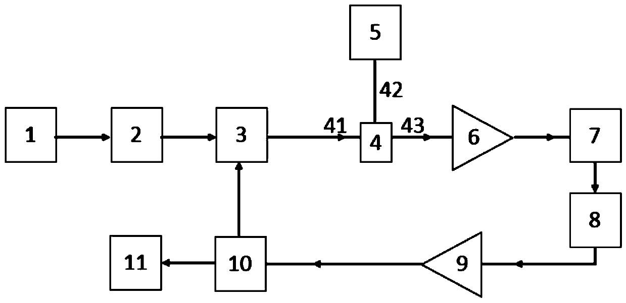
[0030] An optoelectronic oscillator stress sensing system based on nonlinear dispersive elements such as figure 1 As shown, it includes an optical frequency comb 1, a polarization controller 2, an electro-optic modulator 3, a circulator 4, a nonlinear dispersion element 5, an erbium-doped fiber amplifier 6, a photodetector 7, a DC blocker 8, and a low-noise microwave amplifier 9 , a microwave power beam splitter 10, and a digital processing unit 11.

[0031] The specific connection method is: the output end of the optical frequency comb 1 is connected to the input end of the polarization controller 2, the output end of the polarization controller 2 is connected to the optical input end of the electro-optic modulator 3, and the electrical input end of the electro-optic modulator 3 is connected to the microwave One output end of the power beam splitter 10 is connected, the optical output end of the electro-optical modulator 3 is connected with the 41 port of the circulator 4, th...

Embodiment 2

[0045] An optoelectronic oscillator stress sensing system based on nonlinear dispersive elements such as figure 1 As shown, it includes an optical frequency comb 1, a polarization controller 2, an electro-optic modulator 3, a circulator 4, a nonlinear dispersion element 5, an erbium-doped fiber amplifier 6, a photodetector 7, a DC blocker 8, and a low-noise microwave amplifier 9 , a microwave power beam splitter 10, and a digital processing unit 11.

[0046]The specific connection method is: the output end of the optical frequency comb 1 is connected to the input end of the polarization controller 2, the output end of the polarization controller 2 is connected to the optical input end of the electro-optic modulator 3, and the electrical input end of the electro-optic modulator 3 is connected to the microwave One output end of the power beam splitter 10 is connected, the optical output end of the electro-optical modulator 3 is connected with the 41 port of the circulator 4, the...

Embodiment 3

[0060] An optoelectronic oscillator stress sensing system based on nonlinear dispersive elements such as figure 1 As shown, it includes an optical frequency comb 1, a polarization controller 2, an electro-optic modulator 3, a circulator 4, a nonlinear dispersion element 5, an erbium-doped fiber amplifier 6, a photodetector 7, a DC blocker 8, and a low-noise microwave amplifier 9 , a microwave power beam splitter 10, and a digital processing unit 11.

[0061] The specific connection method is: the output end of the optical frequency comb 1 is connected to the input end of the polarization controller 2, the output end of the polarization controller 2 is connected to the optical input end of the electro-optic modulator 3, and the electrical input end of the electro-optic modulator 3 is connected to the microwave One output end of the power beam splitter 10 is connected, the optical output end of the electro-optical modulator 3 is connected with the 41 port of the circulator 4, th...


PUM


Abstract

The invention discloses a nonlinear dispersion element-based photoelectric oscillator stress sensing system, which comprises an optical frequency comb, a polarization controller, an electrooptical modulator, a circulator, a nonlinear dispersion element, an erbium-doped optical fiber amplifier, a photoelectric detector, a DC blocking device, a low-noise microwave amplifier, a microwave power splitter and a digital processing unit. The nonlinear dispersion element is adopted as a sensing unit and a dispersion value is tuned by stress, so that the generated microwave signal frequency is encoded,and the sensing sensitivity and resolution and the demodulation speed can be effectively improved.

Description

technical field [0001] The invention relates to a photoelectric oscillator stress sensing system based on a nonlinear dispersion element, which is suitable for the fields of optical fiber sensing and all-optical information processing. [0002] technical background [0003] Optical fiber sensors, due to their advantages of anti-electromagnetic interference, small size, light weight, and high sensitivity, have received extensive attention in aerospace, building health monitoring, perimeter security, and smart corridors. Among them, the fiber grating sensor is an important fiber optic sensor. By encoding and demodulating the wavelength, it can realize high stability and high reliability sensing of the parameter to be measured, but the resolution of demodulation is often limited by the resolution of optical demodulation instruments such as spectrometers. limitations, and it is not easy to achieve high-speed scanning. However, microwave photonic filters or photoelectric oscillat...

Claims


Application Information

Patent Timeline
Patent Type & Authority Patents(China)
IPC IPC(8): H01S3/067H01S3/108G01L1/24G01L11/02
CPCG01L1/242G01L11/025H01S3/06754H01S3/108
Inventor 刘玲宁提纲裴丽李晶郑晶晶
Owner BEIJING JIAOTONG UNIV
Why Eureka
Try Eureka