Photonic crystal optical fiber

A technology of photonic crystal fiber and fiber, which is applied in the direction of glass fiber, cladding fiber, optical waveguide light guide, etc., can solve the problems of dispersion, effective refractive index difference, inter-mode coupling or crosstalk, etc., and achieve low dispersion, low limit loss, The effect of small nonlinear coefficients

Inactive Publication Date: 2018-08-24
UNIV OF SHANGHAI FOR SCI & TECH
View PDF3 Cites 2 Cited by
  • Summary
  • Abstract
  • Description
  • Claims
  • Application Information

AI Technical Summary

Problems solved by technology

Many optical fibers with special structures have been proposed to support the transmission of OAM modes, but the effective refractive index difference between the modes in these optical fibers is always within 10 -4 order of magnitude and cannot be significantly improved
Since the effective refractive index difference between modes cannot be improved, even and odd eigenmode shifts, birefringence and polarization mode dispersion may occur during OAM mode transmission, which affects the mode purity and causes coupling or crosstalk between modes

Method used


Image

  • Photonic crystal optical fiber
  • Photonic crystal optical fiber
  • Photonic crystal optical fiber

Examples


Embodiment Construction

[0024] In order to make the technical means, creative features, goals and effects of the present invention easy to understand, the following embodiments illustrate a photonic crystal fiber of the present invention in detail with reference to the accompanying drawings.

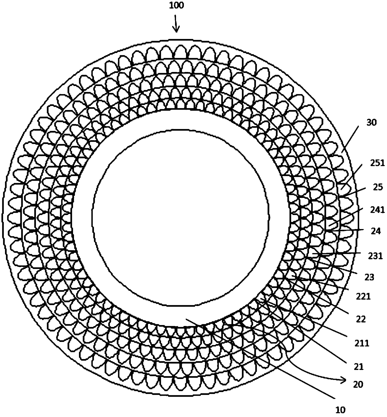
[0025] figure 1 It is a schematic diagram of the cross-sectional structure of a photonic crystal fiber of the present invention.

[0026] The shape of photonic crystal fiber is long and linear. The cross-sectional structure of photonic crystal fiber is as figure 1 As shown, the photonic crystal fiber 100 includes a core layer 10 , a cladding layer 20 and a coating layer 30 from inside to outside. And the core layer 10 , the cladding layer 20 and the coating layer 30 are all concentric.

[0027] The core layer 10 is located in the inner ring of the cross-sectional structure of the photonic crystal fiber 100 . The center of the core layer 10 has a circular hole, the radius of the circular hole is in the range...


PUM


Abstract

The invention discloses a photonic crystal optical fiber which is characterized in that the photonic crystal optical fiber comprises a core layer, a cladding layer and a coating layer from the insideto the outside, the cross section of the optical fiber is circular, the core layer, the cladding layer and the coating layer are concentric, the core layer is located at the innermost layer of the optical fiber, and the center of the cross section of the core layer is a circular hole, a plurality of semi-elliptical air holes are uniformly arranged in the cladding layer, the cladding layer includesfive cladding rings, multiple air holes with the same size are uniformly arranged in each of the cladding rings, the air holes in the cladding rings are in a circular array arrangement with the center of the core layer as a center original point, the sizes of the air holes in the cladding rings are gradually increased from the inner ring to the outer ring, the long axes of the semi-elliptical pores are directed to the center of the core layer, both the core layer and the cladding layer are made of silica crystal or silicon crystal, and the coating layer is made of acrylate or silicone resin.The photonic crystal optical fiber of the invention can transmit a plurality of orbital angular momentum modes, the effective refractive index difference of a mode group reaches an order of 10<-3>, the confinement loss is low, the nonlinear coefficient is small, and the dispersion is low.

Description

technical field [0001] The invention belongs to the field of communication, and in particular relates to a photonic crystal fiber. Background technique [0002] Orbital Angular Momentum (Orbital Angular Momentum) is another important parameter of photons besides the traditional wavelength, polarization and other parameters. With the continuous improvement of technologies such as wavelength division multiplexing, time division multiplexing, and code division multiplexing in the field of optical communication, the amount of data transmitted by traditional optical fibers is close to saturation. OAM provides a A whole new degree of freedom. [0003] In the OAM optical fiber communication system, the optical fiber supporting OAM mode transmission is a key component. Photonic Crystal Fiber (PCF) has attracted widespread attention in recent years. Its cross-section has a complex refractive index distribution, and usually contains pores in different arrangements. The scale of thes...

Claims


Application Information

Patent Timeline
Patent Type & Authority Applications(China)
IPC IPC(8): G02B6/02G02B6/036
CPCG02B6/02328G02B6/02342G02B6/02395G02B6/03611
Inventor 许勋贾宏志雷雨庚志浩刘星刘刚贾春华沈志威王宁涂建坤马志豪柴俊宇陈加骏许涛
Owner UNIV OF SHANGHAI FOR SCI & TECH
Why Eureka
Try Eureka