
MOS type super-barrier rectifier and manufacturing method thereof

A technology of super-barrier rectifiers and manufacturing methods, applied in the field of rectifiers, can solve the problems of MOS structures such as short channels, large epitaxial resistivity, and no great advantages, so as to reduce VF value, reduce resistivity, and improve withstand voltage horizontal effect

Pending Publication Date: 2018-08-28
JIANGSU JIEJIE MICROELECTRONICS
View PDF6 Cites 0 Cited by
  • Summary
  • Abstract
  • Description
  • Claims
  • Application Information

AI Technical Summary

Problems solved by technology

[0003] In order to ensure the breakdown voltage, the MOS type super-barrier rectifier device of the current technology has a large epitaxial resistivity, especially a high-voltage device, and its VF value is relatively high, which does not have much advantage over the ordinary Schottky; and the MOS structure The channel is very short, the reverse leakage is large, and the avalanche capability is weak

Method used


Image

  • MOS type super-barrier rectifier and manufacturing method thereof
  • MOS type super-barrier rectifier and manufacturing method thereof
  • MOS type super-barrier rectifier and manufacturing method thereof

Examples


Embodiment Construction

[0042] The present invention will be described in further detail below in conjunction with the accompanying drawings. What is described below is only the accompanying drawings recorded in the present invention. Those of ordinary skill in the art can also use these accompanying drawings without paying creative work. , to obtain other drawings.

[0043] The present invention shows three injection etchings, but not limited to three times, and all ideas of forming P-type regions based on multiple etching and implantation are within the protection scope of the present invention.

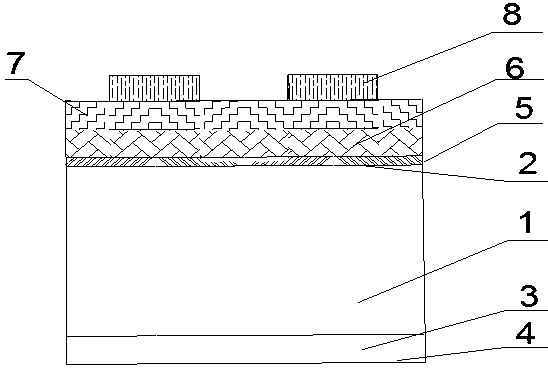
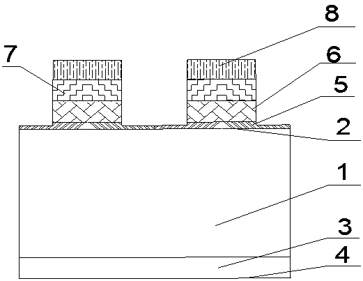
[0044] A MOS type super-barrier rectifier, comprising a semiconductor substrate, the upper part of the semiconductor substrate is an N-type epitaxial layer 1, the surface of which is the first main surface 2, and the lower part of the semiconductor substrate is an N-type epitaxial layer 1. + Type substrate 3, the surface of which is the second main surface 4, the first main surface 2 is provided with inte...


PUM


Abstract

The invention discloses a MOS type super-barrier rectifier, comprising a semiconductor substrate. The upper part of the semiconductor substrate is an N-type epitaxial layer which is a first main surface, and the lower part of the semiconductor substrate is an N+ type substrate, which is a second main surface. A groove is formed in the first main surface, and a grid oxidation layer is arranged on the first main surface, and polycrystalline silicon is arranged on the first main surface, and an N+ region and a P-type region are sequentially arranged in the epitaxial layers on the two sides of thespaced grooves from top to bottom. The manufacturing method comprises the following steps of (1) providing a substrate, and epitaxially growing a layer of epitaxial layer and a thermal growth grid oxidation layer, and depositing a polycrystalline silicon and an oxidation layer; (2) carrying out photo-etching; (3) conducting etching; (4) removing photoresist; (5) injecting N-type impurity arsenicor phosphorus; (6) injecting the P-type impurity boron for the first time and conducting thermal annealing; (7) carrying out etching; (8) injecting the P-type impurity boron for the second time and conducting heat annealing; (9) conducting secondary etching; (10) injecting P-type impurity boron for the third time and carrying out heat annealing; (11) removing the oxidation layer; (12) precipitating a first electrode; (13) precipitating a second electrode. According to the invention, the product performance is improved.

Description

technical field [0001] The invention relates to the field of rectifiers, in particular to a MOS type super-barrier rectifier and a manufacturing method thereof. Background technique [0002] Existing power rectifiers are generally divided into two types, one is a Schottky barrier rectifier device, and the other is a super-barrier rectifier integrated with a MOS channel. Ordinary Schottky barrier rectifiers are made of precious metals (such as gold, silver, etc.) , platinum, titanium, nickel, molybdenum, etc.) are in contact with the semiconductor to form a semiconductor device made of a heterojunction barrier. In order to meet the requirements of the forward voltage drop of different devices, different types of metals are usually selected, and the Increase the complexity of the manufacturing process, the large reverse leakage current leads to high reverse power dissipation, and the need to use precious metal materials to contact the semiconductor, the manufacturing cost is h...

Claims


Application Information

Patent Timeline
Patent Type & Authority Applications(China)
IPC IPC(8): H01L29/78H01L29/06H01L21/336
CPCH01L29/0607H01L29/0684H01L29/66666H01L29/7827
Inventor 殷允超周祥瑞
Owner JIANGSU JIEJIE MICROELECTRONICS
Learn More