Gas supply system and gas supply method

A technology of gas supply system and gas supply device, which is applied in pipeline systems, chemical instruments and methods, gas/liquid distribution and storage, etc. It can solve problems such as inconvenient adjustment, insufficient intake air volume, and influence on intake stability, etc., to achieve Reduced environmental burden, easy installation, and easy operation

Pending Publication Date: 2018-09-07
SUZHOU WEIPENG ELECTRICAL TECH CO LTD
View PDF0 Cites 1 Cited by
  • Summary
  • Abstract
  • Description
  • Claims
  • Application Information

AI Technical Summary

Problems solved by technology

[0003] The traditional glass rotameter is used to measure the gas flow in the commonly used gas supply system. The traditional glass rotameter can only set a fixed parameter at a time. Insufficient flow rate will affect the treatment effect; the traditional glass rotameter needs to be frequently adjusted every time the model is changed and the parameter test is adjusted; the traditional glass rotameter cannot be quantified when adjusting, and each adjustment requires two people , one person adjusts the flowmeter, and the other person check

Method used


Image

  • Gas supply system and gas supply method
  • Gas supply system and gas supply method
  • Gas supply system and gas supply method

Examples


Example Embodiment

[0067] Example 1

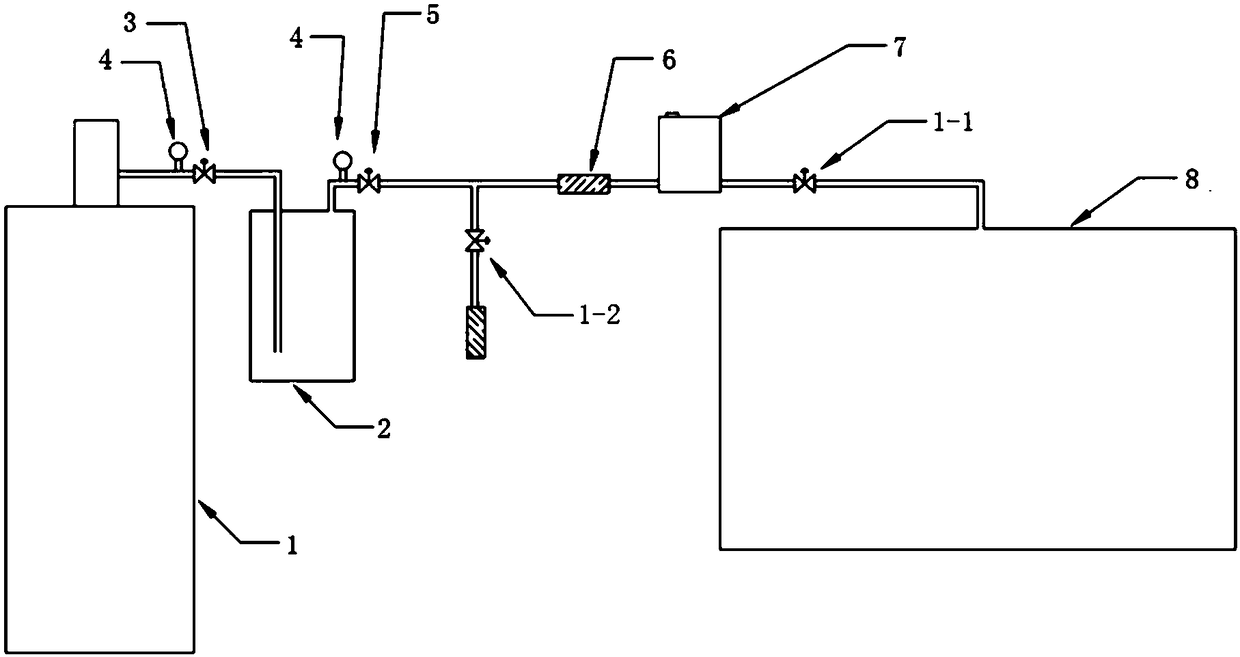
[0068] In this embodiment, the gas supply device uses a gas cylinder, such as figure 2 As shown, a digital pressure gauge 4 is also installed on the pipe E at the outlet of the gas cylinder, which is used to monitor the pressure in the gas cylinder in real time.

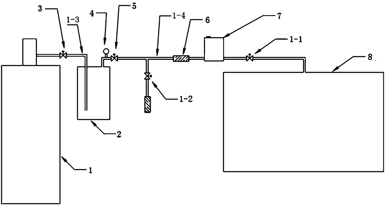
[0069] When this embodiment is used as a gas supply system for a shoe machine, anhydrous monomethylamine gas is stored in the gas cylinder, and the pressure control valve 3 is opened. After the gas in the gas cylinder enters the buffer tank 2, when the pressure in the buffer tank 2 reaches After a certain value (this value is much smaller than the pressure in the cylinder), the buffer tank 2 is completed and the pressure control valve 3 is closed; when the shoe machine runs to the need to enter methylamine, the buffer outlet valve 5 opens, and the gas enters the pipeline F and passes through The gas filter 6, the gas mass flow controller 7, and the flow outlet valve 1-1 enter the shoe machine cavity 8 ...

Example Embodiment

[0071] Example 2

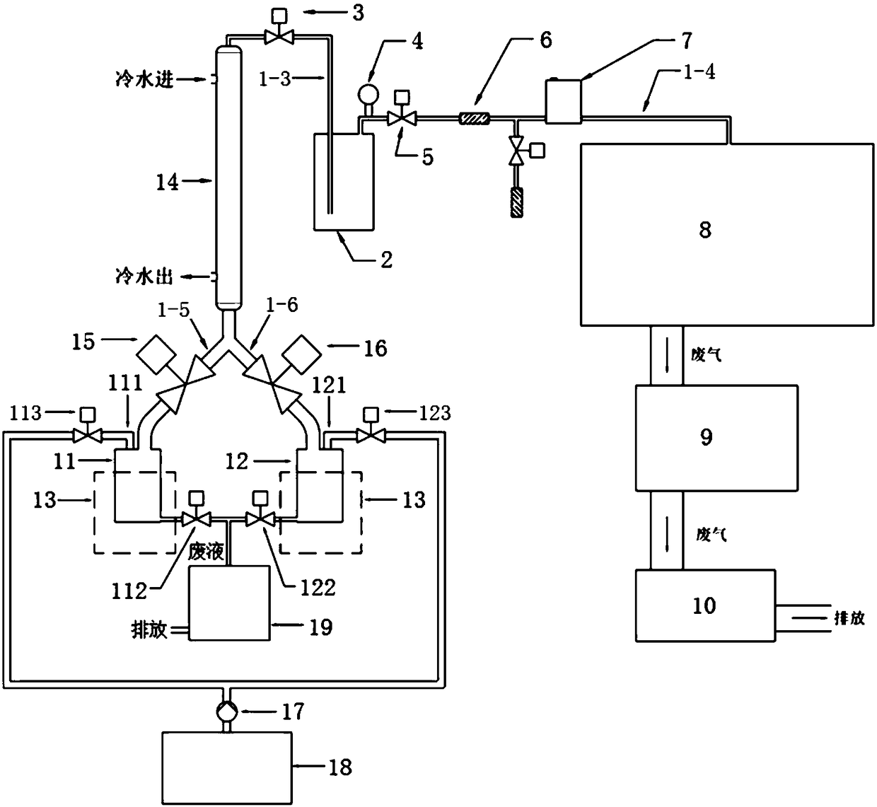
[0072] In this embodiment, the gas supply device adopts a solution heating device, such as image 3 As shown, the gas supply device 1 includes a raw material tank A11, a raw material tank B12, a heating device I12, and a condenser I14. The bottoms of both the raw material tank A and the raw material tank B are equipped with a heating device I. The heating device I is preferably a heat transfer oil heating device ( It can be heated to 60-200℃) or a water bath heating device (can be heated to 60-100℃). The use of heat-conducting oil or water bath heating can effectively control the heating temperature and always stay within a safe range; Condenser I passes through pipe A1-5 and pipe B1 -6 is connected to raw material tank A and raw material tank B, and communicates with the inlet of buffer tank 2 through pipeline E. Pipes A1-5 and B1-6 are respectively equipped with outlet valve A15 and outlet valve B16, raw material tank A and raw materials The top of the tank B...

Example Embodiment

[0083] Example 3

[0084] In this embodiment, the gas supply device adopts a reaction heating device, such as image 3 As shown, the gas supply device 1 includes a raw material tank C11', a raw material tank D12', a reaction tank 13', a condenser II 14', and a heating device II 15'. The raw material tank C and the raw material tank D pass through the pipeline C1-7 and the pipeline D1, respectively. -8 is connected to the reaction tank, the pipe C1-7 is equipped with a raw material valve 16', and the pipe D1-8 is equipped with a stop valve 17'. The reaction tank is connected to the inlet of the condenser II; the bottoms of the raw material tank C and the raw material tank D are both Equipped with weighing module 18'; heating device Ⅱ15' is installed at the bottom of the reaction tank, pressure relief valve 131' is installed on the upper part, a stirrer 132' is installed inside, and the bottom of the reaction tank passes through the waste liquid outlet valve C133' and ultraviolet tr...


PUM


Abstract

The invention discloses a gas supply system and a gas supply method. The gas supply system comprises a gas supply device and a buffer tank. The gas supply device communicates with an inlet of the buffer tank through a pipe E. A pipe F is connected with an outlet of the buffer tank. A pressure control valve is arranged on the pipe E. A digital display pressure gauge and a buffer gas outlet valve are installed on the pipe F on the outlet of the buffer tank respectively. The pipe F is provided with a gas filter and a gas quality and flow controller in sequence. When the gas supply system is usedfor supplying gas to a plasma surface treatment shoe machine, the gas in the gas supply device firstly flows into the buffer tank, so that the pressure of the buffer tank is kept at a stable and low value all the time, it is avoided that gas inlet stability is influenced by gas liquefaction, solid impurities are filtered out by the gas filter, flow of the gas is accurately controlled automaticallyby the gas quality and flow controller, the gas flows into a vacuum chamber of the shoe machine finally, and the whole gas supply system is easy to operate and convenient to install.

Description

technical field [0001] The invention relates to an air supply system and an air supply method thereof. Background technique [0002] In the process of shoe material processing, plasma shoe material surface treatment machine (hereinafter referred to as shoe machine) is needed. The shoe machine uses low-temperature plasma technology to put the shoe material to be processed into the cavity of the shoe machine and pump it to a high vacuum state to form a vacuum chamber. Then the gas catalyst is fed through the gas supply system, and finally the medium-frequency alternating current is applied to ionize the gas in the cavity to form plasma, which bombards the surface of the shoe material and increases the groups on the surface of the shoe material, thereby increasing the adhesion of the glue to the shoe material. [0003] The traditional glass rotameter is used to measure the gas flow in the commonly used gas supply system. The traditional glass rotameter can only set a fixed para...

Claims


Application Information

Patent Timeline
IPC IPC(8): F17D1/04F17D1/20F17D3/01F17D3/16C07C209/84C07C209/00C07C211/04A43D11/00
CPCA43D11/00F17D1/04F17D1/20F17D3/01F17D3/16C07C209/00C07C209/84C07C211/04
Inventor 蔡刚强张仁熙何建才刘亚星周兆龙
Owner SUZHOU WEIPENG ELECTRICAL TECH CO LTD
Why Eureka
Try Eureka