
An oil smoke filtration system

A technology of oil fume filtration and oil fume separator, which is applied in the direction of oil fume removal, dispersed particle filtration, household heating, etc., which can solve the problems of high operating cost, environmental pollution, and low cost, so as to avoid cleaning and maintenance, eliminate air pollution, cost reduction effect

Pending Publication Date: 2018-09-14
乌鲁木齐亚星科创环保科技有限公司
View PDF0 Cites 0 Cited by
  • Summary
  • Abstract
  • Description
  • Claims
  • Application Information

AI Technical Summary

Problems solved by technology

These methods have the defects of high initial investment or high operating cost, or the defects of complicated operation and maintenance, and the defects of incomplete oil fume treatment. Therefore, the smoke exhaust system of the general catering industry needs to be professionally cleaned every six months. Once, but the cleaning of the smoke exhaust system will affect the normal business and the cost is not low
[0005] In summary, the oil fume purification treatment in the catering industry mainly has the problems of incomplete treatment of oil fume, high cost of oil fume purification equipment and troublesome cleaning and maintenance.
On the one hand, cooking fume is an important emission source of PM2.5, which not only pollutes the environment, but also directly affects the life and health of residents; on the other hand, the treatment of cooking fume is a considerable economic expenditure for hotels and restaurants , increasing the operating cost of the catering industry

Method used


Image

  • An oil smoke filtration system
  • An oil smoke filtration system

Examples


Embodiment 1

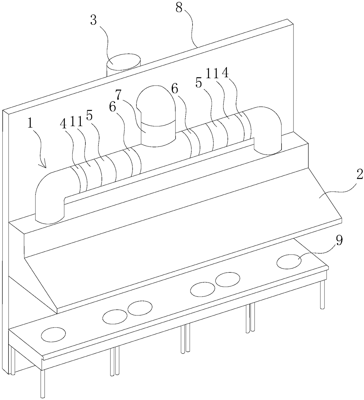
[0036] An oil fume filtering system, comprising an exhaust tube 1, the head end of the exhaust tube 1 is provided with a gas collecting hood 2, the gas collecting hood 2 is located above the stove 9, and the tail end of the exhaust tube 1 is an outer wall discharge end 3 , The oil film device 4, the oil fume separator 5, the modified composite membrane device 6 and the fan 7 are arranged in sequence between the gas collecting hood 2 and the exhaust pipe 1 at the discharge end 3 of the outer wall. In this embodiment, the oil fume separator 5 is a hydrocyclone. The exhaust tube 1 includes two exhaust tubes 11, the head end of each exhaust tube 11 is connected to the gas collecting hood 2, and the tail end of each exhaust tube 11 is connected to the fan 7 , and between the gas collecting hood 2 and the exhaust branch 11 of the fan 7, an oil film device 4, an oil fume separator 5 and a modified composite membrane device 6 are arranged in sequence.

[0037] Preparation of oil film...

Embodiment 2

[0047] An oil fume filtering system, comprising an exhaust tube 1, the head end of the exhaust tube 1 is provided with a gas collecting hood 2, the gas collecting hood 2 is located above the stove 9, and the tail end of the exhaust tube 1 is an outer wall discharge end 3 , The oil film device 4, the oil fume separator 5, the modified composite membrane device 6 and the fan 7 are arranged in sequence between the gas collecting hood 2 and the exhaust pipe 1 at the discharge end 3 of the outer wall. In this embodiment, the oil fume separator 5 is a hydrocyclone. The exhaust tube 1 includes two exhaust tubes 11, the head end of each exhaust tube 11 is connected to the gas collecting hood 2, and the tail end of each exhaust tube 11 is connected to the fan 7 , and between the gas collecting hood 2 and the exhaust branch 11 of the fan 7, an oil film device 4, an oil fume separator 5 and a modified composite membrane device 6 are arranged in sequence.

[0048] Preparation of oil film...

Embodiment 3

[0058] An oil fume filtering system, comprising an exhaust tube 1, the head end of the exhaust tube 1 is provided with a gas collecting hood 2, the gas collecting hood 2 is located above the stove 9, and the tail end of the exhaust tube 1 is an outer wall discharge end 3 , The oil film device 4, the oil fume separator 5, the modified composite membrane device 6 and the fan 7 are arranged in sequence between the gas collecting hood 2 and the exhaust pipe 1 at the discharge end 3 of the outer wall. In this embodiment, the oil fume separator 5 is a hydrocyclone. The exhaust tube 1 includes two exhaust tubes 11, the head end of each exhaust tube 11 is connected to the gas collecting hood 2, and the tail end of each exhaust tube 11 is connected to the fan 7 , and between the gas collecting hood 2 and the exhaust branch 11 of the fan 7, an oil film device 4, an oil fume separator 5 and a modified composite membrane device 6 are arranged in sequence.

[0059] Preparation of oil film...


PUM

PropertyMeasurementUnit
Thicknessaaaaaaaaaa
Ventilation rateaaaaaaaaaa

Abstract

The invention relates to an oil smoke filtration system. The system includes an exhaust cylinder, the head end of the exhaust cylinder is provided with a gas collecting cover, the gas collecting coveris positioned above a stove, the tail end of the exhaust cylinder is an exterior wall discharge end, and an oil filter membrane device, an oil smoke separator, a modification composite membrane device and a blower fan are arranged in order between the gas collecting cover and the exhaust cylinder of the exterior wall discharge end; the oil over membrane of the oil over membrane device is comprised of a fiber glass micropore filtration membrane, a polytetrafluoroethylene membrane and a polyethersulfone membrane which are layered and stacked in order along the direction of oil smoke discharge;the modification composite membrane of the modification composite membrane device is comprised of a polycarbonate membrane, an oxidized graphene filter membrane, a nitrobacteria pellicle and multi-wall carbon nanotubes which are layered and stacked in order along the direction of oil smoke discharge, and the airing rate of the oil over membrane and modification composite membrane are both no lessthan 30%. The removal efficiency of the oil smoke can be reached to 99.6%, the oil smoke can be directly discharged, and the cleaning and maintenance of the smoke evacuation system is avoided.

Description

technical field [0001] The invention relates to kitchen equipment, in particular to an oil fume filtering system. Background technique [0002] Oil fume itself is a serious air pollution. The cooking fume we usually emit is a large amount of thermal oxidation decomposition products produced by cooking oil and food under high temperature conditions. When cooking, the fat is heated. When the temperature reaches the smoking point of edible oil at 170°C, the blue smoke of initial decomposition appears. As the temperature continues to rise, the decomposition speed accelerates. It has a pungent smell, and the particle size of oily fume is between 0.01 micron and 0.3 micron. Relevant departments analyzed the oil fume samples collected from residents’ households and found more than 220 kinds of chemical substances, mainly including aldehydes, ketones, hydrocarbons, fatty acids, alcohols, aromatic compounds, esters, lactones, and heterocycles. compounds etc. Known mutational carc...

Claims


Application Information

Patent Timeline
IPC IPC(8): F24C15/20B01D46/54B01D46/52B01D53/84
CPCB01D46/521B01D46/543B01D53/84F24C15/2035Y02A50/20
Inventor 朱文革郑斌井丹王鹏朱明
Owner 乌鲁木齐亚星科创环保科技有限公司
Learn More