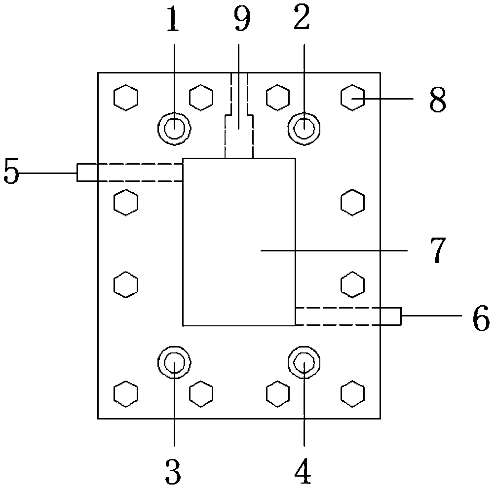
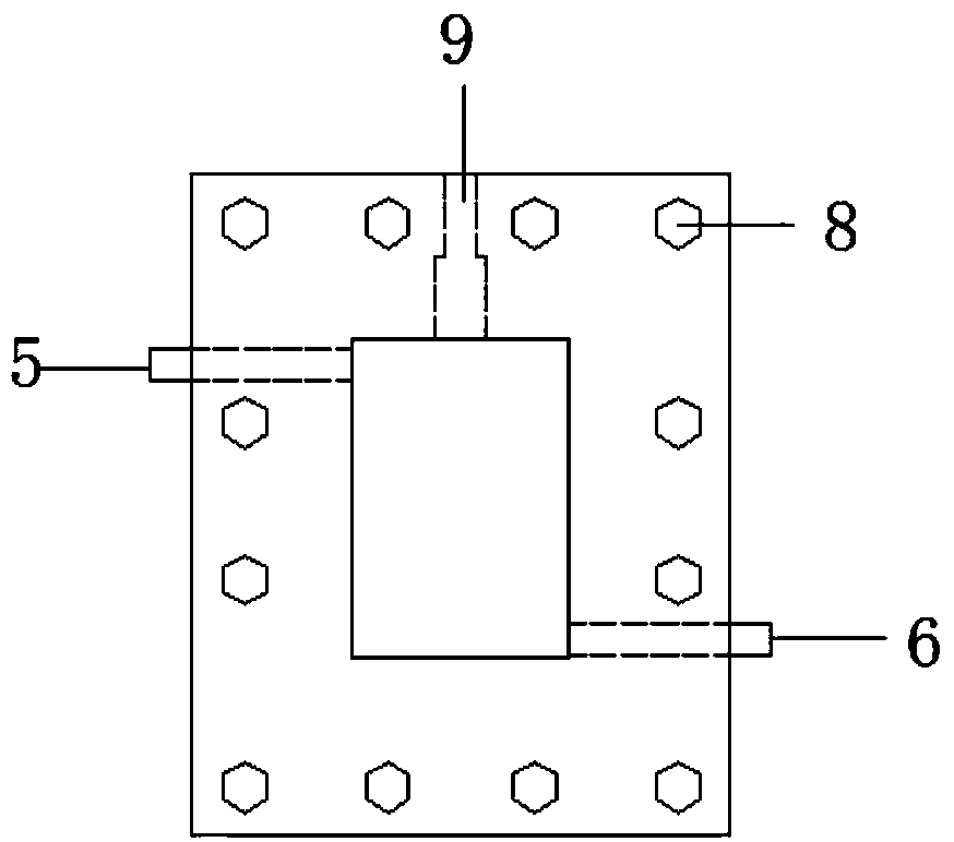
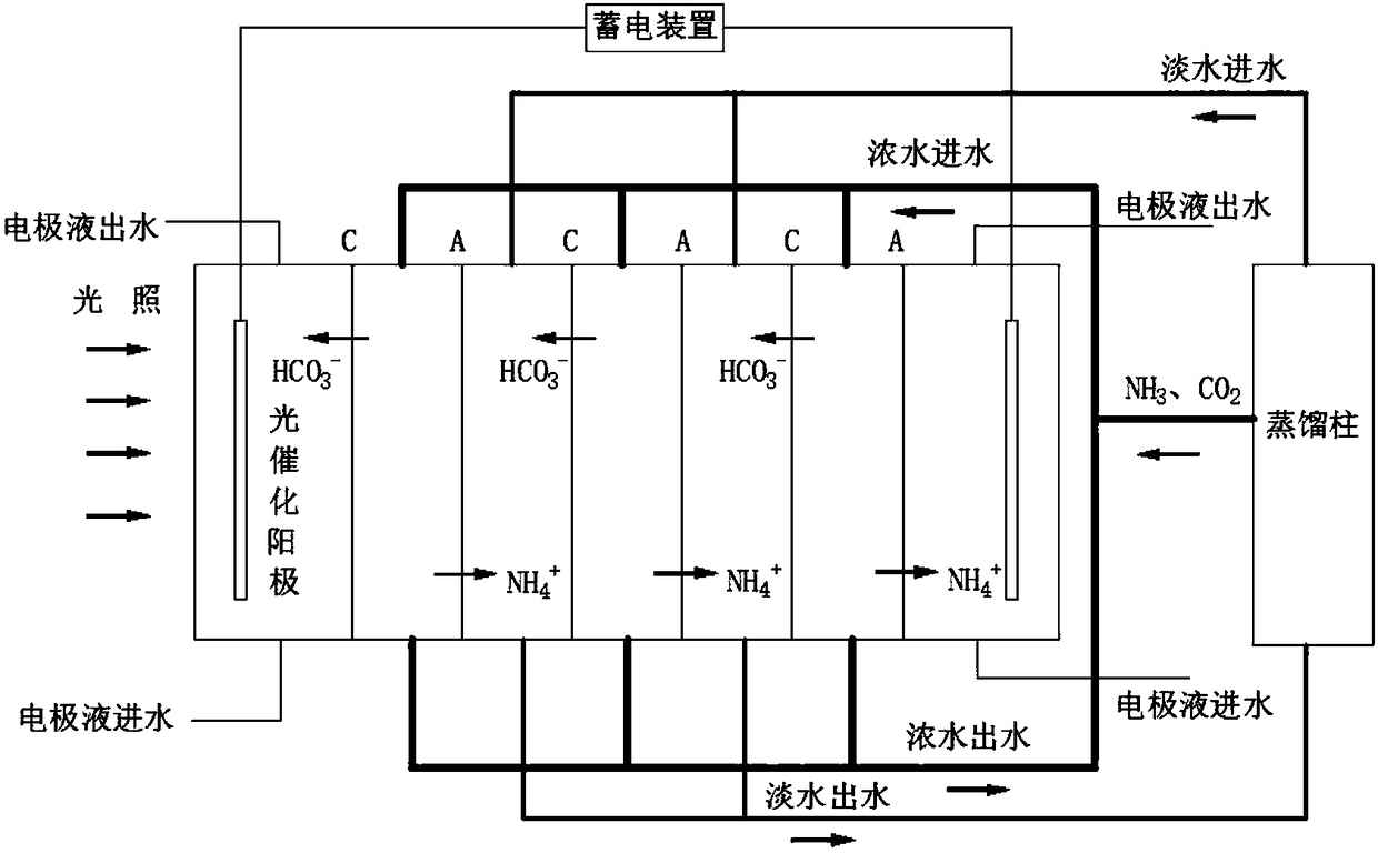
Reverse electrodialysis coupled photocatalytic reactor and applications thereof
A catalytic reactor and reverse electrodialysis technology, applied in chemical instruments and methods, light water/sewage treatment, water/sludge/sewage treatment, etc., can solve unstable electricity production, complicated operation, microbial fuel cell start-up Slow and other problems, to achieve the effect of simple assembly and convenient sampling
- Summary
- Abstract
- Description
- Claims
- Application Information
AI Technical Summary
Problems solved by technology
Method used
Image
Examples
Embodiment 1
[0050] In this example 1, in order to test the degradation power generation efficiency of the coupled reactor, a 300W xenon lamp was used to irradiate, the distance between the light source and the photocatalytic electrode was set to 10cm, the logarithm of the membrane was 20, the concentration of concentrated ammonium bicarbonate was 1.8mol / L, and the light The concentration of ammonium bicarbonate is 0.01mol / L, and the volume of both is 1L. The influent flow rates of concentrated ammonium bicarbonate and light ammonium bicarbonate are both 50mL / min. The anode chamber contains 200mL of rhodamine B with a concentration of 10mg / L and 0.1mol / L sodium sulfate, and another 50mL of the mixed solution is stored in a graduated cylinder connected to the anode chamber, and circulates in the anode chamber through a peristaltic pump to avoid electrode contamination. Inner concentration polarization is also convenient for sampling. The cathode chamber contains 250 mL of water. A 1000Ω r...
Embodiment 2- Embodiment 5
[0051] Embodiment 2-embodiment 5, comparative example 1
[0052] Test according to the method of embodiment 1, only change the water inlet flow velocity of ammonium bicarbonate solution, specifically as table 1, Figure 4 , Figure 5 .
[0053] Table 1
[0054]
[0055] Figure 4 Show the comparison of the degradation efficiency of reverse electrodialysis coupled photocatalytic reactor of the present invention under different feed water flow rates with separate reverse electrodialysis and separate photocatalytic degradation efficiency; Figure 5 The power generation voltages of reverse electrodialysis alone, photocatalysis alone, and reverse electrodialysis coupled with photocatalysis at different flow rates are shown. Changing the water flow rate of the ammonium bicarbonate solution, the degradation and electricity production of the PRC system on rhodamine B are as follows: Figure 4 , Figure 5 shown. When the flow rate of ammonium bicarbonate solution was 25, 50, ...
Embodiment 6- Embodiment 9
[0058] Test according to the method of embodiment 1, only change the concentration of concentrated ammonium bicarbonate solution, specifically as table 2, Image 6 , Figure 7 .
[0059]
[0060] Image 6 Show the degradation efficiency of the reverse electrodialysis coupling photocatalytic reactor of the present invention under different concentrations of concentrated water; Figure 7 Show the output voltage of the reverse electrodialysis coupled photocatalytic reactor of the present invention under different concentrations of concentrated water; change the concentrated ammonium bicarbonate concentration, the degradation and electricity generation of the PRC system to rhodamine B are respectively as follows Image 6 , Figure 7 shown. When the concentrations of concentrated ammonium bicarbonate were 0.5, 1.0, 1.5, and 1.8 M, the degradation rates of PRC to rhodamine B after 2 hours were 21.3%, 22.9%, 24.2%, and 30.5%, respectively. When the concentrations of concentra...
PUM
 Abstract
Description
Claims
Application Information
 - R&D
- Intellectual Property
- Life Sciences
- Materials
- Tech Scout
- Unparalleled Data Quality
- Higher Quality Content
- 60% Fewer Hallucinations
Browse by: Latest US Patents, China's latest patents, Technical Efficacy Thesaurus, Application Domain, Technology Topic, Popular Technical Reports.
© 2025 PatSnap. All rights reserved.Legal|Privacy policy|Modern Slavery Act Transparency Statement|Sitemap|About US| Contact US: help@patsnap.com


