
Grinding technology for ion implantation technology cavity

An ion implantation and grinding process technology, applied in discharge tubes, electrical components, circuits, etc., can solve the problems of difficulty in meeting the vacuum degree of the process chamber, high vacuum degree requirements, etc. sexual effect

Active Publication Date: 2018-09-18
江阴市光科光电精密设备有限公司
View PDF5 Cites 4 Cited by
  • Summary
  • Abstract
  • Description
  • Claims
  • Application Information

AI Technical Summary

Problems solved by technology

The ion implanter consists of 5 parts: ion source, ion extraction and mass analyzer, accelerating tube, scanning system, and process chamber. Since the process chamber needs ion implantation under vacuum conditions, the vacuum degree of the ion implantation process chamber is very demanding. High, but the vacuum degree of the current process chamber is difficult to meet the demand

Method used


Image

  • Grinding technology for ion implantation technology cavity
  • Grinding technology for ion implantation technology cavity
  • Grinding technology for ion implantation technology cavity

Examples


Embodiment 1

[0016] The present invention is a welding process for an ion implantation process cavity, which includes the following process steps for the weldment in sequence: 1. Pretreatment of the weldment before welding; 2. Welding the cavity weldment by gas shielded welding; 3. 1. Treatment of the weldment after welding; the shielding gas used in step 2 is a mixture of argon and hydrogen; in the process of welding the weldment into a cavity in step 2, spot welding is used on the atmospheric side of the cavity. The solder joints on the atmospheric side of the cavity are strip-shaped, and the distance between adjacent solder joints is less than the length of the solder joints. In step 1, use acetone to clean the groove of the weldment and the dirt within 30-50mm from both sides of the groove, and preheat the vacuum chamber to 10°C to ensure a uniform preheating temperature. In step 2, the welding line energy is controlled at 20-25kJ / cm, the welding wire is ER316L, the diameter of the wel...

Embodiment 2

[0018] The only difference from Example 1 is that the electrolyte is a mixed solution composed of 70% by mass of phosphoric acid, 20% of sulfuric acid and 10% of hydrofluoric acid. The mass ratios of argon and hydrogen in the mixed gas are 90% and 10% respectively. Preheat the vacuum chamber to 250°C to ensure uniform preheating temperature.

Embodiment 3

[0020] The only difference from Example 1 is that the electrolyte is a mixed solution composed of 69% phosphoric acid, 28% sulfuric acid and 3% hydrofluoric acid. The mass ratios of argon and hydrogen in the mixed gas are 99.99% and 0.01% respectively; the vacuum chamber is preheated to 100°C to ensure uniform preheating temperature.

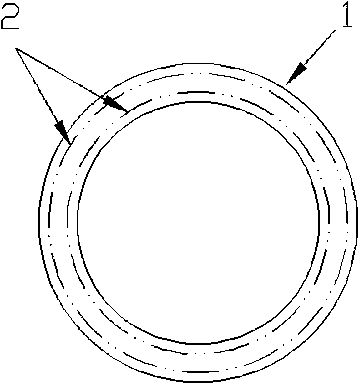
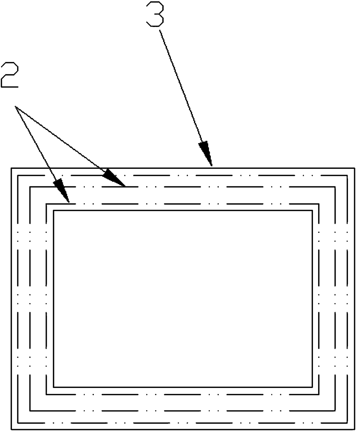
[0021] Such as figure 1 , figure 2 As shown, the schematic diagram of the ground surface texture 2 of the flange surface 1 and the sealing groove 3 after being processed by this process.


PUM

PropertyMeasurementUnit
Diameteraaaaaaaaaa

Abstract

The invention discloses a grinding technology for an ion implantation technology cavity, and the grinding technology comprises the following steps: carrying out the electrolytic grinding, normal pressure cleaning, first high-pressure cleaning, neutralization treatment, second high-pressure cleaning, steam cleaning, third high-pressure cleaning and drying of the sealing surface of the cavity, wherein the electrolyte solution is a mixture of phosphoric acid with the mass percentage of 60 to 70%, sulfuric acid with the mass percentage of 20 to 30%, and hydrofluoric acid with the mass percentage of 3 to 10%. The roughness of the processed ion implantation technology cavity can reach the range of Ra1.0-2.0, and the surface ripples are reduced, thereby reducing the air discharge and more effectively guaranteeing the vacuum degree of the cavity.

Description

technical field [0001] The invention relates to a grinding process for an ion implantation process cavity. Background technique [0002] Ion implanter is the key equipment in the pre-process of integrated circuit manufacturing. Ion implantation is a technique for doping the area near the surface of the semiconductor. The purpose is to change the carrier concentration and conductivity type of the semiconductor. Compared with the conventional thermal doping process, ion implantation can precisely control the implantation dose, implantation angle, implantation depth, lateral diffusion, etc., overcome the limitations of conventional processes, and improve the circuit integration, turn-on speed, yield and life, reducing cost and power consumption. The ion implanter consists of 5 parts: ion source, ion extraction and mass analyzer, accelerating tube, scanning system, and process chamber. Since the process chamber needs ion implantation under vacuum conditions, the vacuum degree o...

Claims


Application Information

Patent Timeline
IPC IPC(8): H01J37/32B23H5/08
CPCB23H5/08H01J37/32412H01J37/32458
Inventor 瞿一涛
Owner 江阴市光科光电精密设备有限公司
Learn More