
Precision pressure control system and hydraulic machining method of servo pump control hydraulic machine

A technology of precision pressure and control system, used in hydraulic processing of hydraulic presses, precision pressure control systems, and hydraulic presses. Pressure oscillation, to achieve the effect of timely response

Active Publication Date: 2018-09-21
江苏扬力液压装备有限公司
View PDF7 Cites 5 Cited by
  • Summary
  • Abstract
  • Description
  • Claims
  • Application Information

AI Technical Summary

Problems solved by technology

When using servo pump control, there are both pump port pressure sensor and master cylinder upper chamber pressure sensor. The sensor uses voltage signal which is not only susceptible to interference but also difficult to troubleshoot.
Under high-frequency operation, the impact noise is louder when the pressure is released, which may easily cause loosening of the fixing parts

Method used


Image

  • Precision pressure control system and hydraulic machining method of servo pump control hydraulic machine
  • Precision pressure control system and hydraulic machining method of servo pump control hydraulic machine

Examples


Embodiment Construction

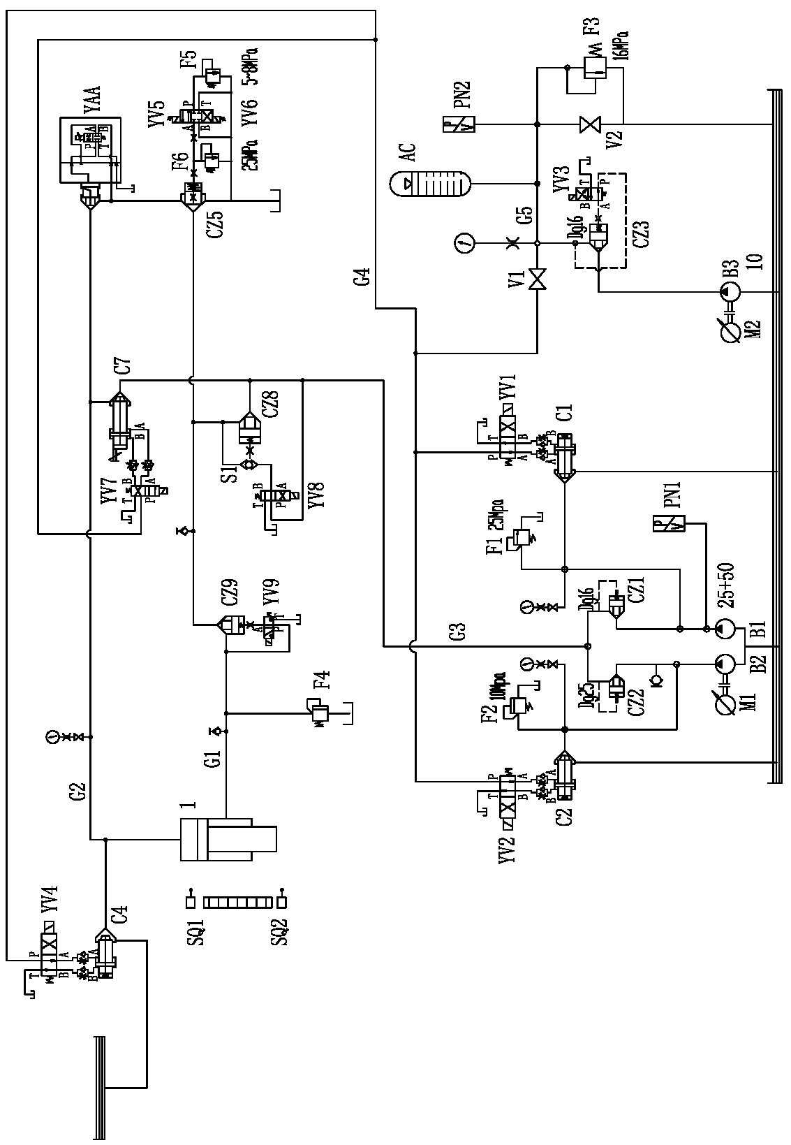
[0023] Such as figure 1 As shown, the precision pressure control system of the servo pump control hydraulic press of the present invention includes a master cylinder 1 installed above the slider, the lower chamber of the master cylinder 1 is connected with the oil passage G1 of the lower chamber of the master cylinder, and the upper chamber of the master cylinder 1 is connected with the master cylinder. The upper cavity of the cylinder is connected to the oil circuit G2, and also includes the medium flow servo pump B1 and the large flow servo pump B2 jointly driven by the servo motor M1. The outlet of the medium flow servo pump B1 is connected with the inlet of the cartridge valve CZ1, and the large flow servo pump The outlet of the pump B2 is connected to the inlet of the second cartridge valve CZ2, the hydraulic control ports of the first cartridge valve CZ1 and the second cartridge valve CZ2 are respectively connected to their respective outlets, and the outlets of the first...


PUM


Abstract

The invention relates to a precision pressure control system and a hydraulic machining method of a servo pump control hydraulic machine. The hydraulic machine comprises a medium-flow servo pump and alarge-flow servo pump driven by a servo motor, outlet pipelines of two pumps are connected with a main cylinder upper cavity oil way through a seventh dynamic valve, and the main cylinder upper cavityoil way is further connected with an oil tank through a fourth dynamic valve and a proportional valve; a main cylinder lower cavity pipeline is connected with an outlet of a ninth cartridge valve, aninlet of the ninth cartridge valve is connected with the oil tank through a fifth cartridge valve and an eighth cartridge valve, the fifth cartridge valve supplies supporting force during deceleration and pressurization through an overflow valve, and the eighth cartridge valve is turned on during the return stroke. In hydraulic machining, each working cycle comprises the following actions of automatic pressure compensation for an energy accumulator, pressure supplementation stopping for the energy accumulator, rapid descending of a sliding block, deceleration pressurizing of the sliding block, pressure maintaining of the sliding block, pressure relief of the sliding block, and return and stopping of the sliding block. The servo driver is switched in two modes of flow control and PID regulation control, stable pressurization of the sliding block is achieved, the phenomenon that a part deforms due to pressurization overshoot is avoided, and pressure relief is stable.

Description

technical field [0001] The invention relates to a hydraulic machine, in particular to a precision pressure control system of a servo pump-controlled hydraulic machine. The invention also relates to a hydraulic processing method of a hydraulic machine, which belongs to the technical field of machine tool control systems. Background technique [0002] In the normal process mode of the hydraulic press, there are two control methods: fixed range and constant pressure. The fixed range state is controlled by the stop position of the slider, while the constant pressure state is the pressure value generated after the slider drives the upper mold and the lower mold to completely close. However, in the state of constant pressure, the rapid downward movement of the slider and the transition to the working movement are controlled by the position signal, so in the constant pressure mode, the position feedback is used to control at first, and then switch when the actuator is in contact wit...

Claims


Application Information

Patent Timeline
Patent Type & Authority Applications(China)
IPC IPC(8): F15B11/028F15B11/08F15B1/02F15B21/08
CPCF15B1/02F15B11/028F15B11/08F15B21/08F15B2211/20584
Inventor 不公告发明人
Owner 江苏扬力液压装备有限公司
Learn More