Cutting balloon and balloon catheter

A technology for cutting balloons and balloons, which is applied in the direction of balloon-shaped catheters, catheters, and surgical cutting instruments. Less damage and increased friction

Active Publication Date: 2018-09-28
DK MEDICAL TECH CO LTD
View PDF6 Cites 24 Cited by
  • Summary
  • Abstract
  • Description
  • Claims
  • Application Information

AI Technical Summary

Problems solved by technology

After balloon dilation, the single-cut guidewire cuts the lesion into a single slit, and then melts the plaque through the action of subsequent drugs, but it has little effect on highly calcified lesions
[0012] The application number is CN201310135128.4 Chinese patent discloses a cutting balloon dilatation catheter with drugs loaded on the surface of the balloon. The cutting balloon dilation catheter includes a cutting balloon catheter body and a drug coating, wherein the cutting balloon catheter body includes a balloon The surface of the balloon is provided with multiple blades, and the surface of the balloon and the blades is coated with a drug coating, but the balloon may cause greater damage to the intima when the balloon is expanded and cut, and the blades have poor passability. Poor, the passability of the overall system is poor
[0013] The Chinese patent with the application number CN201610266377.0 discloses a balloon catheter, which includes a needle hub, a proximal catheter, a distal catheter, a balloon, and a catheter tip connected in sequence. The balloon catheter also includes two inherent guide wires and one The guide wire, the balloon catheter uses the guide wire as a natural guide wire, which reduces the number of natural guide wires. Only one end is fixed, so it will migrate during the process, and the expected effect cannot be achieved, especially the guide wire and inherent guide wire of the longer balloon are easy to be displaced or entangled during the cutting process

Method used


Image

  • Cutting balloon and balloon catheter
  • Cutting balloon and balloon catheter
  • Cutting balloon and balloon catheter

Examples


Embodiment 1

[0075] Provide the schematic diagram of the balloon catheter as shown in 7, where 1 is the end tube, 2 is the inner tube, 3 is the balloon body, 4 is the guide wire, 5 is the cutting wire, 6 is the catheter, 7 is the developing ring, 8 is Y-shaped connector, 9 is the filling port of the balloon, and 10 is the outlet of the guide wire.

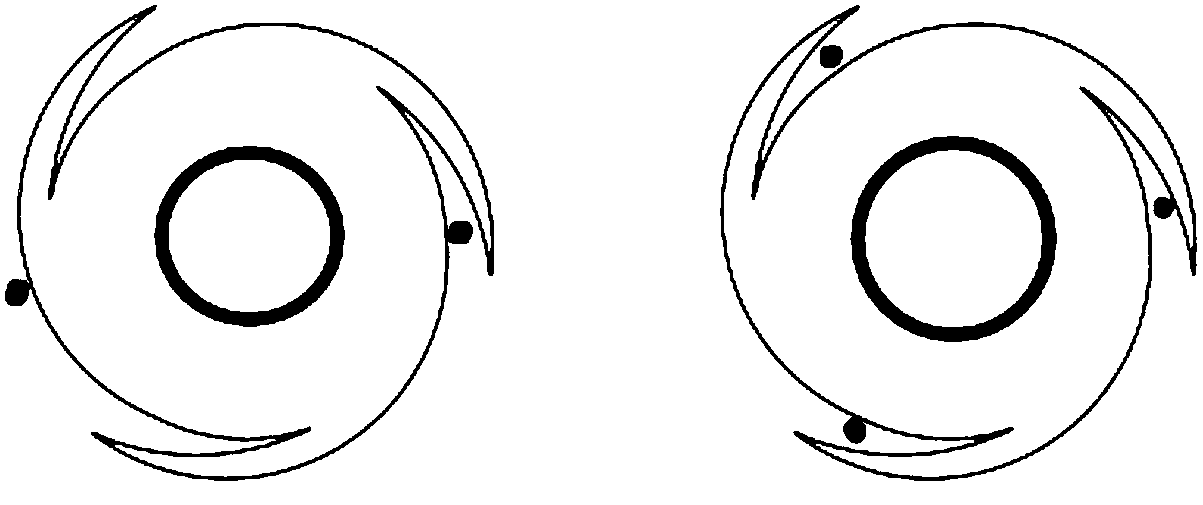
[0076] Such as Figure 7 As shown, the balloon 3 is connected to the catheter 6 by means of laser welding, etc., and the catheter 6 is a double-lumen tube made of polyether block acyl (PEBAX), and its cross-sectional structure schematic diagram is shown in Figure 8 As shown, its first channel 11 is circular, used to guide the guide wire to pass through, it is connected with the inner tube 2 and its inner diameter is not less than 0.30 mm, and it is more preferable that its inner diameter can be at least 0.014 inch, 0.018 inch, 0.035 inch Guide wires 4 of three specifications are passed through. The outer cutting wires 5 of the balloon body 3...

Embodiment 2

[0080] The schematic diagram of the balloon catheter is provided as shown in 9. This embodiment is consistent with the embodiment 1 except for the pushing part and the connecting piece, so it will not be repeated here. Figure 9 Among them, 1 is the terminal tube, 2 is the inner tube, 3 is the balloon, 4 is the guide wire, 5 is the cutting wire, 6 is the catheter, 7 is the developing ring, 8 is the connector, 9 is the filling port of the balloon, and 10 is the Quick exchange guide wire port

[0081] Such as Figure 9 As shown, the balloon 3 is connected to the catheter 6 by means of laser welding or the like. The distal end of the inner tube 2 passes through the interior of the balloon body 3, and is connected with it at the distal end of the balloon to form a sealing point for the cavity of the balloon. The inner tube 2 can allow the guide wire 4 to pass through its lumen, and the commonly used nominal specifications of the guide wire 4 are 0.014 inches, 0.018 inches, and 0...


PUM


Abstract

The invention provides a cutting balloon which comprises a balloon body and a cutting wire, wherein the cutting wire is arranged in the radial direction of the outer surface of the balloon body, the two ends of the cutting wire are respectively fixed on the two ends of the balloon body, and the cutting wire comprises a foldable structure. Compared with the prior art, the cutting balloon has betterpassing ability as the flexible cutting wire is arranged on the surface of the cutting balloon; furthermore, the cutting balloon can cut plaque tissues in expansion and has small damage to inner membranes; meanwhile, the cutting wire is fixed to the surface of the cutting balloon or can slide in the telescopic direction, so that the problem of displacement or winding in a cutting process is avoided; furthermore, the foldable structure not only can provide axial length compensation for the cutting wire in expansion of the balloon, but also can improve friction between the balloon body and blood vessel walls; thus, the balloon is prevented from displacement.

Description

technical field [0001] The invention belongs to the technical field of balloons, in particular to a cutting balloon and a balloon catheter. Background technique [0002] Percutaneous coronary intervention (PCI) is an important means of revascularization treatment for coronary heart disease. The number of patients with coronary heart disease undergoing PCI in my country is also increasing year by year. The technical update of interventional devices and the improvement of surgical skills have made more patients with coronary heart disease Patients benefit from it. The instruments that need to be used in PCI include guide catheter, guide wire, balloon and stent, etc. The guide wire is the track for the instruments to pass through the coronary artery lesion during PCI, and it is one of the important factors that determine the success of PCI. The balloon is the main tool for dilating coronary lesions, relieving vascular stenosis and ensuring the smooth placement of stents. [00...

Claims


Application Information

Patent Timeline
Patent Type & Authority Applications(China)
IPC IPC(8): A61B17/3209A61M29/00A61M25/10
CPCA61B17/3209A61B2017/00778A61B2017/32096A61M29/00A61M25/10181A61B17/320725A61B2017/22061A61M2025/1086A61M2025/109A61M25/0026A61M25/09A61M25/1002A61M2025/1004A61M2025/105A61M2025/1093
Inventor 翁玉麟牛冬子刘宝瑞石全曹苹王晓炜
Owner DK MEDICAL TECH CO LTD
Why Eureka
Try Eureka