SOI substrate and method of forming SOI substrate
A substrate, silicon substrate technology, applied in electrical components, electrical solid devices, circuits, etc., can solve the problems of low heat conduction efficiency, device saturation drive current drop, application limitations of SOI technology, etc., achieve good heat dissipation performance, solve self-heating Problems, the effect of promoting heat transfer
- Summary
- Abstract
- Description
- Claims
- Application Information
AI Technical Summary
Problems solved by technology
Method used
Image
Examples
Embodiment 1
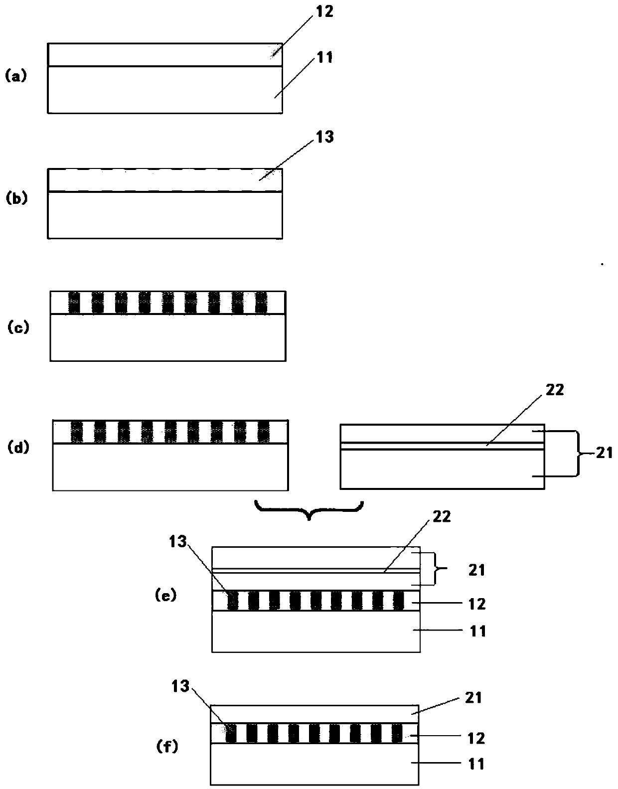
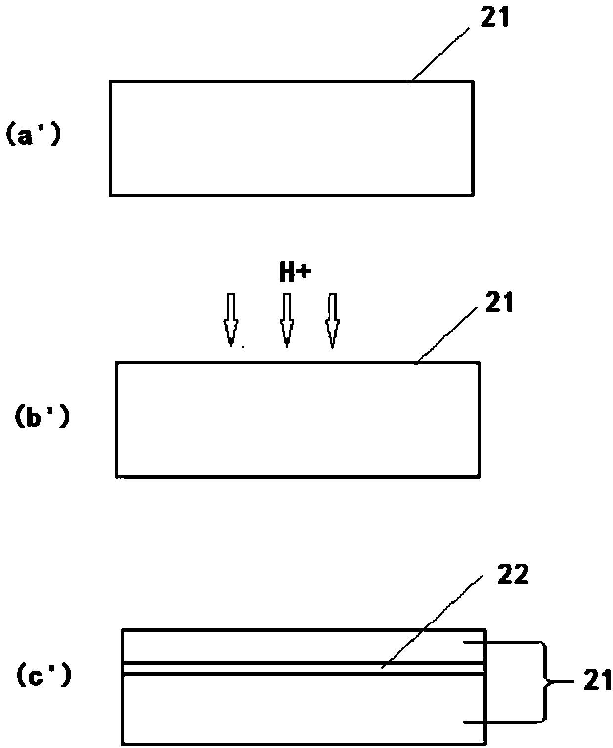
[0060] refer to figure 2 , the method for forming the SOI substrate in this embodiment includes:
[0061] Step a: providing a first silicon substrate 11 , and forming a first dielectric layer 12 on the upper surface of the first silicon substrate 11 .
[0062] In this embodiment, the first dielectric layer 12 is a silicon oxide insulating layer formed by thermally oxidizing the upper surface of the first silicon substrate 11 .
[0063] Step b: forming at least one groove 13 with an open top in the first dielectric layer 12 , and the thickness of the first dielectric layer 12 at the bottom of the groove is greater than or equal to zero and less than a set value.
[0064]In this embodiment, at least one groove 13 with an opening at the top is formed in the first dielectric layer 12 by the following method: using photolithography to define the shape and size of the groove, and dry etching from the top of the first dielectric layer 12 Etching is started, and the etching is stop...
Embodiment 2
[0077] The present invention also provides an SOI substrate, referring to figure 2 f, SOI substrate includes bottom silicon 11, buried oxide layer 12 on bottom silicon 11, top layer silicon 21 on buried oxide layer 12, buried oxide layer 12 includes at least one groove 13 with an open top, buried oxide layer at the bottom of the groove The thickness is greater than or equal to zero and less than a set value; the groove 13 is filled with insulating and heat-conducting materials.
[0078] By introducing a thermally conductive material with a higher thermal conductivity than the buried oxide layer 12 into the buried oxide layer 12, the heat conduction of the buried oxide layer is promoted, the self-heating problem of the SOI structure is solved, and the heat dissipation performance of the SOI structure is improved.
[0079] The insulating and heat-conducting material is preferably an AlN material with good insulating ability and good heat dissipation ability.
[0080] When the ...
Embodiment 3
[0085] Figure 7 It is a flowchart of a method for forming an SOI substrate according to a third embodiment of the present invention. The difference between this method and the method of the first embodiment is that the thermally conductive material filled in step c is a non-insulating thermally conductive material, and In step d, an insulating and heat-conducting layer 14 is formed on the upper surface of the first dielectric layer 12 .
[0086] Graphene powder or graphite film can be deposited in the tank 13 by one of PVD, CVD, and solution methods.
[0087] Before forming the AlN thin film, it is preferable to perform CMP polishing on the first dielectric layer 12 so as to obtain a high-quality AlN thin film.
PUM
 Abstract
Description
Claims
Application Information
 - R&D
- Intellectual Property
- Life Sciences
- Materials
- Tech Scout
- Unparalleled Data Quality
- Higher Quality Content
- 60% Fewer Hallucinations
Browse by: Latest US Patents, China's latest patents, Technical Efficacy Thesaurus, Application Domain, Technology Topic, Popular Technical Reports.
© 2025 PatSnap. All rights reserved.Legal|Privacy policy|Modern Slavery Act Transparency Statement|Sitemap|About US| Contact US: help@patsnap.com


