Xenon lamp power supply system with trigger pre-combustion device and operation method
A power supply system and pulsed xenon lamp technology, applied in the field of laser amplifiers and pulsed xenon lamp power supply systems, can solve the problems of poor optical output stability, poor anti-interference, complex structure, etc., to improve optical stability, reduce electromagnetic interference, and extend xenon lamp. effect of life
- Summary
- Abstract
- Description
- Claims
- Application Information
AI Technical Summary
Problems solved by technology
Method used
Image
Examples
Embodiment 1
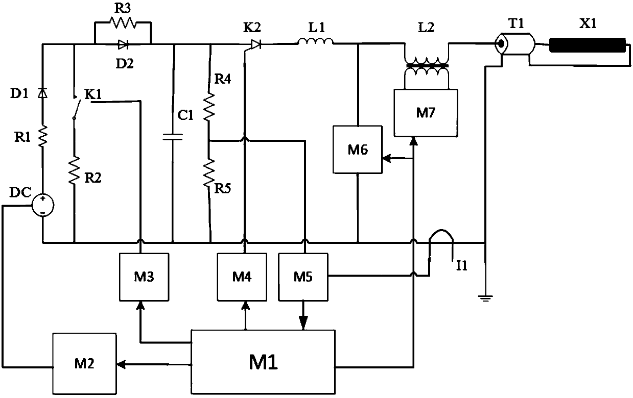
[0042] Example 1 is as figure 1 A pulse xenon lamp power supply system with a trigger pre-ignition device is shown. The power supply system includes a master controller M1, a DC power supply branch, a discharge protection branch, a pulse forming branch, a trigger pre-ignition branch, and a discharge switch tube Drive branch, data acquisition branch, xenon lamp load X1;
[0043] The output terminal of the master controller M1 is connected to the input terminals of the DC power supply branch, the protection and discharge branch, the pulse forming branch, and the trigger pre-ignition branch. The input terminal of the master controller M1 is connected to the input terminal of the data acquisition branch. The output terminal is connected;
[0044] The DC power supply branch is used to generate a DC charging current according to a control signal; the DC current branch is composed of a charging control unit M2, a DC charger DC, a current limiting resistor R1 and a high voltage protection ...
Embodiment 2
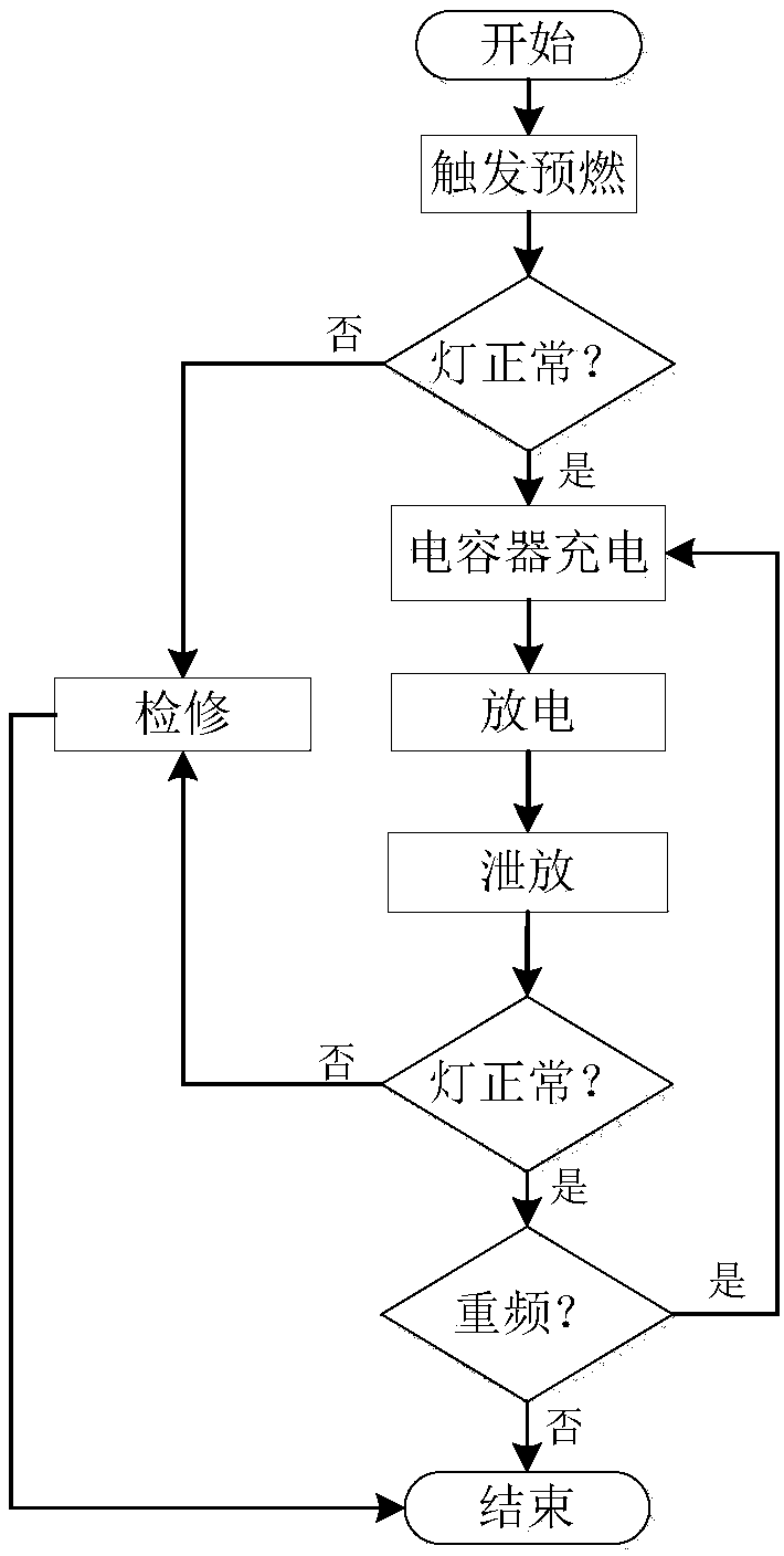
[0053] Embodiment 2 is an operating method of a pulse xenon lamp power supply system with a trigger pre-ignition device. The power supply system can be the power supply system in any of the embodiments in Embodiment 1. The operating method includes the following steps:
[0054] Step S1, the system is initialized. First, the overall controller M1 and each control unit are initialized, and the charging voltage setting value of the DC charger DC and the charging current setting value of the pre-combustion unit M6 are set;
[0055] Step S2, start the trigger pre-combustion branch to make the xenon lamp X1 enter the pre-combustion steady state;
[0056] The start trigger pre-ignition branch is to send a pre-ignition signal through the main controller M1 to start the pre-ignition unit M6. After a certain time delay, a trigger signal is given to the trigger unit M7. After the trigger unit M7 receives the trigger signal Start to start and supply a high voltage to the magnetic switch L2 to ge...
Embodiment 3
[0068] In this embodiment, the use and operation method of the pulsed xenon lamp power supply system and the operation flow of the circuit are illustrated based on specific circuits. The pulsed xenon lamp power supply system is consistent with the power supply system in any of the foregoing embodiments. The capacity of the capacitor C1 is 350µF, the inductance of the wave-modulating inductor L1 is 90µF, the discharge switch tube K2 uses a thyristor, the secondary side of the magnetic switch L2 has an inductance of 7mH before saturation, and 20µF after saturation. The cable T1 uses a coaxial cable.
[0069] The specific circuit operation is as follows:
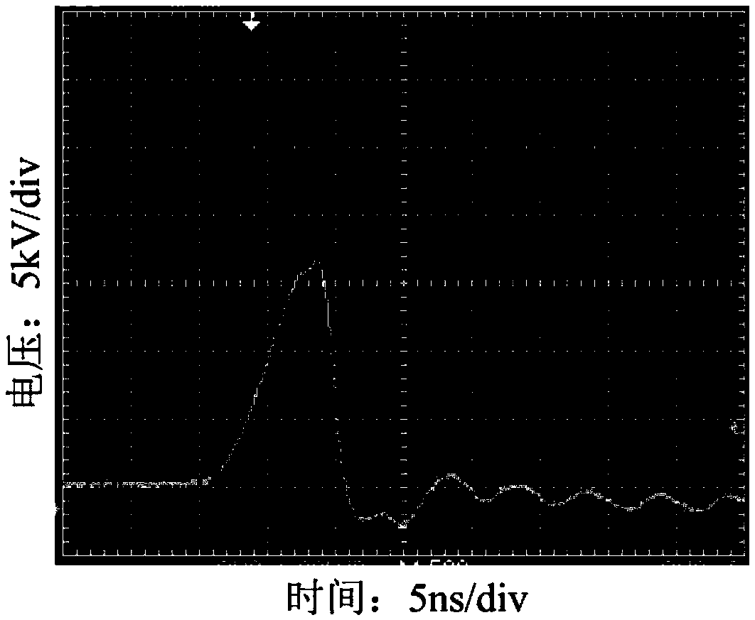
[0070] First, initialize the main controller M1 and each control unit, set the constant current output of the DC motor DC to 200mA, set the charging setpoint voltage to 3kV, and set the constant current output of the pre-combustion module to 150mA. Then, the master controller M1 sends a pre-ignition signal to make the pre-combustion...
PUM
 Abstract
Description
Claims
Application Information
 - R&D
- Intellectual Property
- Life Sciences
- Materials
- Tech Scout
- Unparalleled Data Quality
- Higher Quality Content
- 60% Fewer Hallucinations
Browse by: Latest US Patents, China's latest patents, Technical Efficacy Thesaurus, Application Domain, Technology Topic, Popular Technical Reports.
© 2025 PatSnap. All rights reserved.Legal|Privacy policy|Modern Slavery Act Transparency Statement|Sitemap|About US| Contact US: help@patsnap.com


