Furnace cover of carbon calcinations single furnace

A calcination and monomer technology, applied in furnaces, furnace components, carbon preparation/purification, etc., can solve the problems of inability to eliminate the influence of heat, easy to accumulate heat, and reduce the utilization rate of heat, and achieve the effect of eliminating heat on the furnace cover. Influence, improve calcination efficiency, accelerate the effect of cooling process

Inactive Publication Date: 2018-10-26
湖南省长宁炭素股份有限公司
View PDF7 Cites 0 Cited by
  • Summary
  • Abstract
  • Description
  • Claims
  • Application Information

AI Technical Summary

Problems solved by technology

[0002] The calciner is one of the main thermal equipment for carbon production, which belongs to the high-energy-consuming industrial kiln equipment. Most of the existing calciners are horizontal structures, and there are also a small number of vertical structures with small volumes. The furnace cover is made of steel Composed of skeleton and refractory materials, in the actual production and use process, the maximum temperature of the furnace cover surface reaches above 140 degrees Celsius, the heat loss is large, and the service life is short, and the furnace cover of the existing calciner is also easy to accumulate a part Calcined carbon products are generally placed far away from the furnace cover, which reduces the utilization rate of heat and is not conducive to eliminating the influence of heat on the furnace cover.
[0003] In recent years, especially after 2005, with the development and application of new materials and technologies, the furnace cover of the calciner is mostly made of ceramic fiber modules anchored and installed, which has the advantages of small thermal conductivity, low capacity, and small heat loss. However, the one-time cost is relatively high. Before 2005, the furnace cover of the calciner was basically made of refractory lightweight clay bricks. Most domestic carbon companies are still using it. The advantages are low cost and simple construction. But the disadvantage is that the thermal conductivity of refractory bricks is high, and it increases with the temperature of the furnace chamber. During long-term high-temperature use, the refractory bricks shrink and deform, and gaps appear between them, resulting in a large loss of negative pressure in the furnace chamber and heat loss. More loss, resulting in excessive waste of energy
[0004] Therefore, the carbon industry has continuously explored and innovated the construction technology of the calciner cover, and adopted a series of measures to insulate it. The earliest use was to cover light bricks with diatomite bricks. The advantage is weight. It is lighter, but the integrity is poor, and the sealing is not good, so it has been eliminated; the second is to use light pouring material to spread evenly on the surface of the refractory brick. However, as the production temperature changes repeatedly, the castable has poor thermal shock resistance, cracking, falling off, etc., and the insulation effect cannot be achieved; The surface of the brick is covered by smearing. It is composed of refractory fiber powder, additives, binders, etc. It has a good thermal insulation effect, but the disadvantage is that it is low in strength, easy to fall off, and has a short service life.
[0005] CN103591805B announces a ring-type roaster furnace cover and its manufacturing method. The furnace cover structure includes an arch body placed on the steel structure skeleton, and an insulating layer is compounded on the arch body. The arch body is built by several pieces of light-weight special-shaped refractory bricks The thermal insulation layer includes aluminum silicate fiber layer, metal screen and sealing layer. This patent has certain advantages such as sealing performance, refractoriness, corrosion resistance and long service life, but the overall quality of the patent is still relatively heavy. It is inconvenient to open and close the operation. The exposed insulation layer of this patent will not only cause damage to the insulation layer, but also easily cause deformation. The refractory brick masonry process is also time-consuming and labor-intensive. Attention will easily lead to the final size not meeting the requirements, and the patent is not convenient for opening holes on the furnace cover, assembling other auxiliary equipment, etc., and the service life needs to be further improved; in addition, the patent does not solve the problem of heat concentration. The problem of low heat utilization rate due to the location of the furnace cover, and the influence of heat on the furnace cover cannot be eliminated

Method used


Image

  • Furnace cover of carbon calcinations single furnace

Examples


Embodiment Construction

[0020] In order to facilitate the understanding of the present invention, the present invention will be described more fully and in detail below in conjunction with the accompanying drawings and preferred embodiments, but the protection scope of the present invention is not limited to the following specific embodiments.

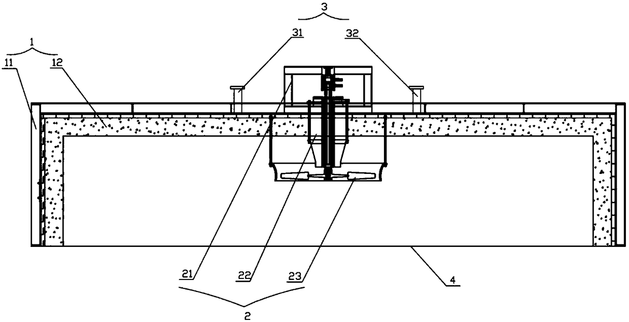
[0021] like figure 1 As shown, a furnace cover of a single carbon calcination furnace includes a cover body 1 and a disturbance fan 2 on the cover body 1. The cover body 1 is an inverted U-shaped structure, and the curved angles of the inverted U-shaped structure are all 90°. The disturbance fan 2 is installed on the upper part of the cover body 1, and the cover body 1 is provided with a cooling air channel 3 with a sealing cover plate.

[0022] In this embodiment, the cover body 1 includes a steel skeleton 11 and an insulating layer 12. The insulating layer 11 is arranged inside the steel skeleton 12. Both the steel skeleton 11 and the insulating layer 12 ha...


PUM

PropertyMeasurementUnit
thicknessaaaaaaaaaa
angleaaaaaaaaaa

Abstract

The invention discloses a furnace cover of a carbon calcinations single furnace. The furnace cover comprises a cover body and a disturbance fan arranged on the cover body; the cover body is of an inverted-U-shaped structure, the bending positions of the inverted-U-shaped structure are 90 degrees, the disturbance fan is arranged on the upper portion of the cover body, and the cover body is providedwith a cooling air flue with a seal cover plate. The influence of heat on the furnace cover can be eliminated, the service life of the furnace cover is prolonged, the utilization rate of heat in theblast furnace can be improved, and energy is saved.

Description

technical field [0001] The invention relates to the field of carbon production equipment, in particular to a furnace cover of a single carbon calcination furnace. Background technique [0002] The calciner is one of the main thermal equipment for carbon production, which belongs to the high-energy-consuming industrial kiln equipment. Most of the existing calciners are horizontal structures, and there are also a small number of vertical structures with small volumes. The furnace cover is made of steel Composed of skeleton and refractory materials, in the actual production and use process, the maximum temperature of the furnace cover surface reaches above 140 degrees Celsius, the heat loss is large, and the service life is short, and the furnace cover of the existing calciner is also easy to accumulate a part Calcined carbon products are generally placed away from the furnace cover, which reduces the utilization rate of heat and is not conducive to eliminating the influence of...

Claims


Application Information

Patent Timeline
Patent Type & Authority Applications(China)
IPC IPC(8): F27D1/18C01B32/05
CPCC01B32/05F27D1/1808Y02P20/10
Inventor 王新华潘文剑陈红吴志刚欧军辉
Owner 湖南省长宁炭素股份有限公司
Why Eureka
Try Eureka