Deep flue gas waste heat recovery system

A flue gas waste heat and recovery system technology, applied in the field of waste heat recovery, can solve the problems of equipment and auxiliary equipment damage, liquid leakage on the low temperature side, and failure to design according to long-term deep acid dew corrosion resistance, so as to increase the economic benefits and heat of the enterprise Accurate calculations, saving installer effects

Pending Publication Date: 2018-11-09
FAW VOLKSWAGEN AUTOMOTIVE CO LTD
View PDF0 Cites 0 Cited by
  • Summary
  • Abstract
  • Description
  • Claims
  • Application Information

AI Technical Summary

Problems solved by technology

[0007] On the one hand, if the original waste heat recovery method wants to further increase the amount of waste heat recovery, it cannot be realized due to the limitation of design parameters such as the inability to change the heat load of the heat exchanger.
On the other hand, the materials of the heat exchanger tubes and shells originally designed did not take into account that they often work near the acid dew point, nor were they designed for long-term resistance to deep acid dew corrosion. Recycling is clearly inappropriate
[0008] On the other hand, in some occasions where the flue gas waste heat recovery device is applied, the working environment is very harsh, and the material and wall thickness of the heat exchanger tube are unreasonably selected. Once the flue gas washes out the heat exchanger tube and leaks, it will cause The leakage of liquid to the surroundings will cause unforeseen damage to the surrounding equipment and auxiliary machines, resulting in large economic losses, which is not allowed by the user

Method used


Image

  • Deep flue gas waste heat recovery system
  • Deep flue gas waste heat recovery system
  • Deep flue gas waste heat recovery system

Examples


Embodiment Construction

[0046] The technical solutions of the present invention will be clearly and completely described below in conjunction with the accompanying drawings. Apparently, the described embodiments are part of the embodiments of the present invention, but not all of them. Based on the embodiments of the present invention, all other embodiments obtained by persons of ordinary skill in the art without making creative efforts belong to the protection scope of the present invention.

[0047] In the description of the present invention, it should be noted that the terms "center", "upper", "lower", "left", "right", "vertical", "horizontal", "inner", "outer" etc. The indicated orientation or positional relationship is based on the orientation or positional relationship shown in the drawings, and is only for the convenience of describing the present invention and simplifying the description, rather than indicating or implying that the referred device or element must have a specific orientation, ...


PUM


Abstract

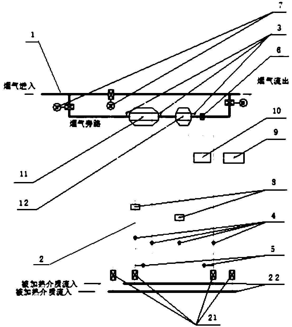
The invention discloses a deep flue gas waste heat recovery system. The deep flue gas waste heat recovery system comprises a flue gas pipeline, a circulating pipeline and a control system, wherein a main waste heat heat-exchange device and a deep waste heat heat-exchange device are sequentially arranged on the flue gas pipeline in the discharge direction of gas; the circulating pipeline comprisesa water inlet pipe communicating with the water inlet end of a pipeline of fluid to be heated and a water outlet pipe communicating with the water outlet end of the pipeline of the fluid to be heated,two branches are correspondingly arranged the other ends of a water inlet pipe and a water outlet pipe, and the two branches separately communicate with the main waste heat heat-exchange device and the deep waste heat heat-exchange device; and the control system comprises a thermocouple temperature measuring device, a mass flowmeter, a water temperature sensor, a smoke acid dew point meter, a flue gas electric regulating valve group, an electric circulating water pump, a man-machine interface interactive device and a PLC unit, and the thermocouple temperature measuring device, the mass flowmeter, the water temperature sensor, the smoke acid dew point meter, the flue gas electric regulating valve group, the electric circulating water pump, the man-machine interface interactive device and the PLC unit are connected in a signal mode. The deep flue gas waste heat recovery system can maximally recover flue gas waste heat, improves the economy of a project and the comprehensive thermal efficiency of waste heat recovery, and finally achieves the purposes of significant energy saving and efficiency enhancement.

Description

technical field [0001] The invention relates to the technical field of waste heat recovery, in particular to a deep flue gas waste heat recovery system. Background technique [0002] The waste heat recovery and utilization technology of high-temperature flue gas and waste gas is a relatively mature waste heat utilization technology, which is widely used in the high-temperature flue gas of coal-fired and natural gas boilers, and the waste heat recovery and utilization of high-temperature waste gas of incinerators. [0003] In the industrial boiler system, the efficiency of the boiler is closely related to the exhaust gas loss item. The exhaust gas loss has always been the bottleneck affecting the improvement of the boiler efficiency. Generally, the heat taken away by the exhaust gas accounts for about 8% of the total input heat of the boiler. Under normal circumstances, the exhaust gas temperature of the boiler is in the range of 140 to 180 ° C. Due to reasons such as unreaso...

Claims


Application Information

Patent Timeline
IPC IPC(8): F27D17/00F23J15/06F24H9/20
CPCF23J15/06F24H9/20F27D17/004Y02E20/30Y02P10/25
Inventor 苑伟彬孙桂林王艳萍朱洪雷吕斌孙丹青罗丹
Owner FAW VOLKSWAGEN AUTOMOTIVE CO LTD
Why Eureka
Try Eureka