Automatic switching power supply device for power failure

A power supply device and automatic switching technology, which is applied in the direction of circuit devices, emergency power supply arrangements, electrical components, etc., can solve the problems of voltage sag, equipment freezing, low applicability, etc., and achieve fast switching speed and convenient replacement Effect

Active Publication Date: 2018-11-13
JIANGXI TUOWANG ELECTRIC
View PDF3 Cites 6 Cited by
  • Summary
  • Abstract
  • Description
  • Claims
  • Application Information

AI Technical Summary

Problems solved by technology

[0002] With the increase of power consumption, the load of the power generation system of the power company can no longer meet the needs of the power consumption of the power consumer, resulting in the power generation system of the power company often tripping due to the overload of power consumption, which is very easy to damage electrical products
[0003] At present, in order to save costs, factories and enterprises generally adopt single power supply control. When the single power supply is cut off, the equipment will not operate normally, production will be shut down, and the equipment may be stuck, which will bring certain economic benefits to factories and enterprises. Loss, the traditional dual power supply control is generally switched by pressing the switch. The delay time of pressing is longer, which will cause voltage sag and short-term power failure, which is easy to affect the quality of electric energy and has low applicability.

Method used


Image

  • Automatic switching power supply device for power failure
  • Automatic switching power supply device for power failure
  • Automatic switching power supply device for power failure

Examples


Embodiment Construction

[0026] The following examples are for illustrative purposes only and are not intended to limit the scope of the invention.

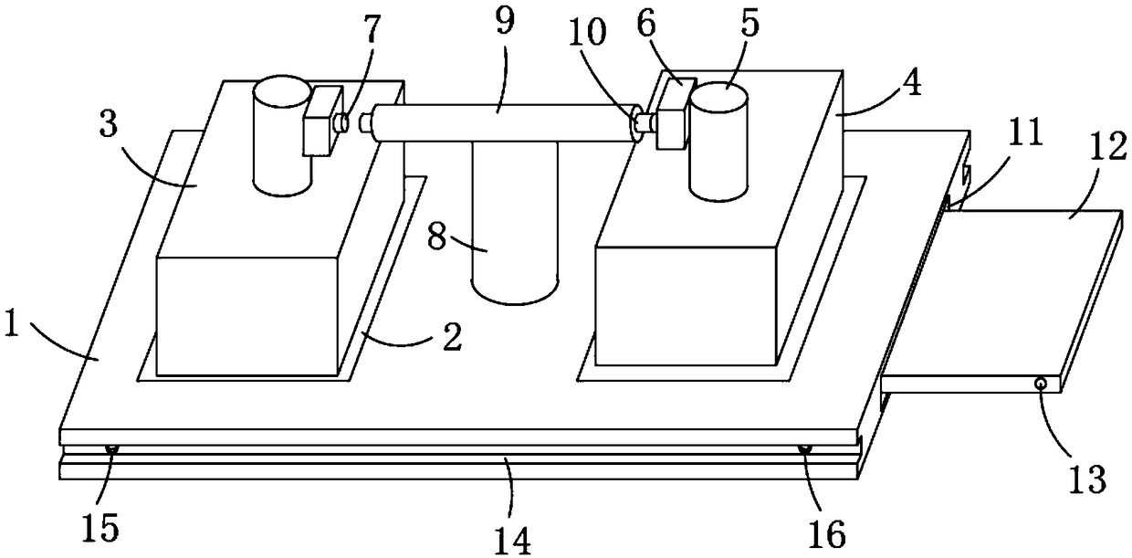
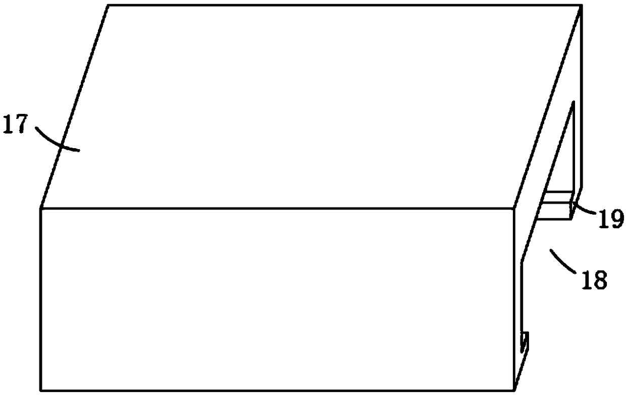
[0027] refer to Figure 1-6 , a power-off automatic switching power supply device, comprising a mounting plate 1 and a housing 17 matching the mounting plate 1, slide grooves 14 are provided on both side walls of the mounting plate 1, and the lower side walls of the housing 17 are provided with Through groove 18 is arranged, and the both side walls of through groove 18 are provided with the flanging 19 that matches with the size and position of chute 14, and housing 17 is installed by sliding in chute 14 by flanging 19, effectively It reduces the accumulation of dust falling on the mounting plate 1, and setting the through groove 18 facilitates the smooth passage of the components on the mounting plate 1 when the housing 17 is installed, and at the same time facilitates ventilation on both sides to ensure heat dissipation.

[0028] The mounting plate 1 ...


PUM


Abstract

The invention discloses an automatic switching power supply device for a power failure. The automatic switching power supply device comprises a mounting plate and a shell matched with the mounting plate; a main power supply and an emergency power supply are arranged on the mounting plate; and a switching mechanism is arranged between the main power supply and the emergency power supply. The automatic switching power supply device has the advantages that the movement of a permanent magnet and a moving rod is realized through magnetic adsorption between two electromagnets and the permanent magnet after the two electromagnets are electrified, when a fault appears in the main power supply, the permanent magnet and the moving rod are adsorbed through the magnetism of the electromagnets to movetowards the emergency power supply, and then the connection of an electrical contact and an electric contact end is completed, so that automatic switching from the main power supply to the emergency power supply is completed, the device is driven by magnetic force, the switching speed is high, high delay of a traditional pressing switch is avoided, the structure is stable, and the quality of electric energy is guaranteed.

Description

technical field [0001] The invention relates to the technical field of power supply control, in particular to an automatic switching power supply device when power is off. Background technique [0002] With the increase of electricity consumption, the load of the power generation system of the power company can no longer meet the needs of the electricity consumption of the power consumer, so that the power generation system of the power company often trips due to the overload of electricity consumption, and it is easy to damage the electrical products. [0003] At present, in order to save costs, factories and enterprises generally adopt single power supply control. When the single power supply is cut off, the equipment will not operate normally, production will be shut down, and the equipment may be stuck, which will bring certain economic benefits to factories and enterprises. Loss, the traditional dual power supply control is generally switched by pressing the switch. The...

Claims


Application Information

Patent Timeline
Patent Type & Authority Applications(China)
IPC IPC(8): H02J9/06
CPCH02J9/06Y02B70/30Y04S20/20
Inventor 王清玉
Owner JIANGXI TUOWANG ELECTRIC
Why Eureka
Try Eureka