Oriented high silicon steel strip and efficient annealing-mode preparation method thereof

A high-silicon steel and thin strip technology, applied in the field of metallurgy, can solve problems such as insufficient precipitation, large temperature difference between the inside and outside of the rolled annealed steel ring, and limited addition of grain boundary segregation elements.

Active Publication Date: 2018-11-16
NORTHEASTERN UNIV
View PDF10 Cites 2 Cited by
  • Summary
  • Abstract
  • Description
  • Claims
  • Application Information

AI Technical Summary

Problems solved by technology

[0004] Japanese patents (Shao 63-069917, 63-089622) have obtained oriented high-silicon steel strips with a thickness of 0.2-0.3 mm by means of hot rolling-warm rolling-cold rolling, using MnS, AIN, TiC or VC as inhibitors, B 8 =1.65T,P 10/50 ≈0.15W/kg; Japanese patents (Ping 4-080321, 224625, 362134) adopt low-temperature heating AlN scheme and later nitriding treatment method, magnetic performance B 8 =1.62~1.67T; Chinese patent (CN104911322 A) also uses nitriding treatment to add inhibitors to enhance the inhibitory force, magnetic performance B 8 =1.55~1.61T; Chinese patent (CN104372238 A) uses a special thin strip continuous casting process to optimize structure-texture-inhibitor, but there are problems such as unstable cast strip quality, serious surface oxidation of cast strip, and complicated equipment maintenance
[0005] The above secondary recrystallization annealing process for oriented high-silicon steel adopts the traditional slow heating and coiling process, which has the following problems: ①The temperature difference between the inside and outside of the coiled annealing steel ring is large, and the secondary recrystallization is uneven; ②The annealing cycle is as long as dozens Hours, high energy

Method used


Image

  • Oriented high silicon steel strip and efficient annealing-mode preparation method thereof
  • Oriented high silicon steel strip and efficient annealing-mode preparation method thereof
  • Oriented high silicon steel strip and efficient annealing-mode preparation method thereof

Examples


Embodiment 1

[0073] An oriented high-silicon steel thin strip, the composition of the thin strip is shown in Table 1 by weight percentage, and the balance is Fe and other unavoidable impurities.

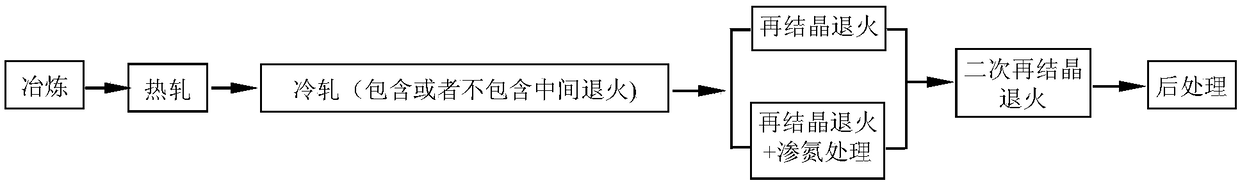
[0074] A method for preparing a high-efficiency annealing mode of an oriented high-silicon steel strip, comprising the steps of:

[0075] step 1:

[0076] Smelt according to the set composition of 9 groups of oriented high-silicon steel thin strips in Table 1, and die-cast into slabs at 1440-1600 °C;

[0077] Step 2:

[0078] Heating the slab to 1250°C for a holding time of 90 minutes; then performing hot rolling with a starting temperature of 1150°C and a final rolling temperature of 950°C to obtain a hot-rolled sheet with a thickness of 2.2mm;

[0079] Step 3:

[0080] Pickling the hot-rolled plate to remove the oxide layer;

[0081] Step 4:

[0082] The hot-rolled plate after pickling is rolled by the second cold rolling method, the first rolling reduction rate is 70%, the rolling tempera...

Embodiment 2

[0094] An oriented high-silicon steel thin strip, the thin strip composition by weight percentage is: Si: 4.5%, C: 0.05%, Als: 0.03%, N: 0.006%, Mn: 0.08%, Cu: 0.5%, S : 0.007%, Nb: 0.15%, V: 0.005%, Sn: 0.06%, Mo: 0.05%, Cr: 0.1%, and the balance is Fe and other unavoidable impurities.

[0095] A method for preparing a high-efficiency annealing mode of an oriented high-silicon steel strip, comprising the steps of:

[0096] step 1:

[0097] Smelted according to the set composition of oriented high-silicon steel thin strip, molded into slab at 1500℃;

[0098] Step 2:

[0099] Heating the slab to 1280°C for a holding time of 30 minutes; then performing hot rolling at a starting temperature of 1200°C and a final rolling temperature of 1050°C to obtain a hot-rolled sheet with a thickness of 3 mm;

[0100] Step 3:

[0101] The hot-rolled sheet is subjected to normalization treatment, the temperature during the normalization treatment is 800°C, the time is 600min, and then water...

Embodiment 3

[0112] An oriented high-silicon steel thin strip, the composition of the thin strip by weight percentage is: Si: 7.0%, C: 0.1%, Als: 0.05%, N: 0.003%, Mn: 0.1%, Cu: 0.5%, S : 0.035%, Nb: 0.4%, V: 0.1%, Mo: 1.0%, Cr: 1.0%, B: 0.5%, and the balance is Fe and other unavoidable impurities.

[0113] A method for preparing a high-efficiency annealing mode of an oriented high-silicon steel strip, comprising the steps of:

[0114] step 1:

[0115] Smelted according to the set composition of oriented high-silicon steel thin strip, and molded into slabs at 1440°C;

[0116] Step 2:

[0117] Heating the slab to 1200°C for a holding time of 120 minutes; then performing hot rolling at a starting temperature of 1120°C and a final rolling temperature of 900°C to obtain a hot-rolled sheet with a thickness of 1.5mm;

[0118] Step 3:

[0119] The hot-rolled sheet is subjected to normalization treatment, the temperature during the normalization treatment is 1200°C, the time is 1min, and then ...


PUM

PropertyMeasurementUnit
Thicknessaaaaaaaaaa
Thicknessaaaaaaaaaa
Average grain diameteraaaaaaaaaa

Abstract

An oriented high silicon steel strip and an efficient annealing-mode preparation method thereof belong to the technical field of metallurgy. The oriented high silicon steel strip comprises the following ingredients (by weight): 4.5-7.0% of Si, C being less than or equal to 0.1%, 0.005-0.05% of Als, 0.003-0.01% of N, 0.03-0.3% of Mn, Cu being less than or equal to 0.5%, 0.003-0.035% of S, 0.02-0.4%of Nb, 0.005-0.1% of V, and the balance Fe and impurities. The method comprises the following steps: casting according to the composition design to obtain a slab, hot-rolling, carrying out acid pickling, cold-rolling after acid pickling, carrying out decarburizing annealing on the slab, carrying out nitriding treatment, and finally carrying out secondary recrystallization annealing. By controlling an inhibitor system, the rolling technology and the annealing technology, short-process annealing-mode preparation of the oriented high silicon steel is realized, production efficiency is raised, production cost is reduced, and the product has excellent comprehensive performance and is thinner in thickness.

Description

technical field [0001] The invention belongs to the technical field of metallurgy, and in particular relates to a preparation method of an oriented high-silicon steel strip and a high-efficiency annealing mode thereof. Background technique [0002] Oriented silicon steel is mainly used in the iron core of power electronic devices such as transformers and ballasts, and is characterized by high magnetic induction along the rolling direction of the steel plate. High-silicon steel generally refers to iron-silicon alloys with a Si content greater than 4.5wt%. As the Si content increases, the magnetic permeability of oriented high-silicon steel increases, and the electrical conductivity and magnetostriction coefficient decrease, especially when the Si content is 6.5wt%. The hysteresis expansion coefficient tends to zero, so the grain-oriented high-silicon steel has significant advantages of low iron loss and low noise at high frequencies. Therefore, oriented high-silicon steel ha...

Claims


Application Information

Patent Timeline
IPC IPC(8): C21D1/26C21D1/74C21D8/12C21D9/52C22C38/00C22C38/02C22C38/04C22C38/06C22C38/12C22C38/16C22C38/34C22C38/42C22C38/44C22C38/46C22C38/48C22C38/54C22C38/60C23C8/26
CPCC21D1/26C21D1/74C21D8/1222C21D8/1233C21D8/1255C21D8/1266C21D8/1272C21D9/52C22C38/001C22C38/008C22C38/02C22C38/04C22C38/06C22C38/12C22C38/16C22C38/34C22C38/42C22C38/44C22C38/46C22C38/48C22C38/54C22C38/60C23C8/26
Inventor 沙玉辉雷蕃左良张芳常松涛
Owner NORTHEASTERN UNIV
Why Eureka
Try Eureka