Flexible current collector battery and production method thereof

A flexible current collector and fluid battery technology, applied in electrolyte battery manufacturing, final product manufacturing, sustainable manufacturing/processing, etc., can solve problems such as hidden dangers of lithium-ion battery safety, fragmentation affecting the use effect, and affecting the quality of lithium-ion battery products. , to ensure the cycle effect and safety performance, solve the problem of easy tearing, and solve the effect of easy oxidation defects

Pending Publication Date: 2018-11-16
DYNABAT NEW ENERGY SCI & TECH CO CLD FUJIAN
View PDF11 Cites 3 Cited by
  • Summary
  • Abstract
  • Description
  • Claims
  • Application Information

AI Technical Summary

Problems solved by technology

[0005] (3) The metal matrix current collector is easy to tear during the manufacturing process of lithium-ion batteries, causing fragments to affect its use effect and affect the safety of lithium-ion batteries; (4) Metal matrix current collectors are prone to appear in the lithium-ion battery manufacturing process Burrs bring safety hazards to lithium-ion batteries; (5) The metal substrate is directly used as a current collector. Due to its smooth surface, the binding force between it and the active material is poor, causing the positive and negative active materials to fall off, which affects the products of lithium-ion batteries quality
[0006] In order to solve the defect that the metal matrix is ​​directly used as the current collector of lithium-ion batteries, the inventor proposed a new type of current collector lithium-ion battery and its manufacturing method through research and development. Fluid defects

Method used


Image

  • Flexible current collector battery and production method thereof
  • Flexible current collector battery and production method thereof
  • Flexible current collector battery and production method thereof

Examples


Embodiment 1

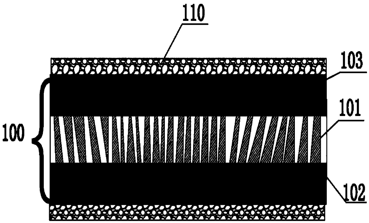
[0049] as attached figure 1 The shown flexible current collector 100 includes at least one polymer material layer 101 as a base layer; at least one porous ceramic layer 102 attached to the base layer; and at least one conductive coating 103 attached to the porous ceramic layer 102 .

[0050]In the above technical solution, the lithium ion battery product of the present invention uses a new material layer to replace the traditional metal matrix to make a lithium battery electrode current collector, which solves the problem of poor bonding between the traditional metal matrix current collector and the active material layer. For the use of flexible current collector electrodes, the peel strength between the flexible current collector and the active material is 3-6N / m compared with the peel strength between the metal matrix current collector and the active material is 0.2-1.5N / m. The binding force between the current collector and the active material layer is significantly improve...

Embodiment 2

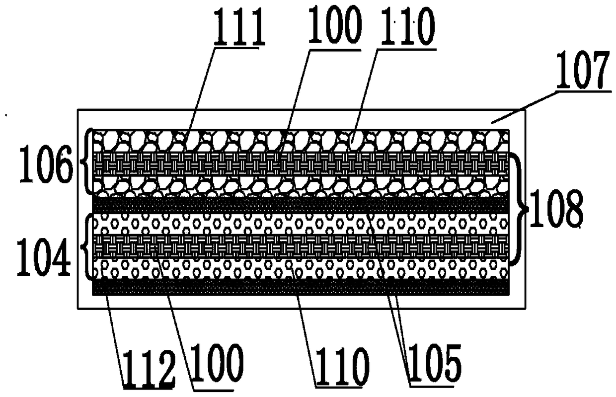
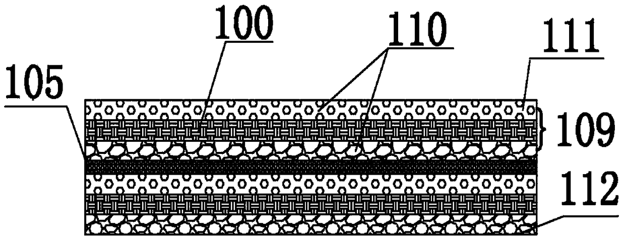
[0052] combined with figure 1 And attached figure 2 As shown, a flexible current collector battery: including at least one set of flexible current collector positive and negative electrodes 108; at least one diaphragm placed between the flexible current collector positive electrode 104 and the flexible current collector negative electrode 106; The electrolyte solution of the fluid electrodes 104, 106 and the diaphragm 105; and a battery case 107 covering the flexible current collector electrodes 104, 106, the diaphragm 105 and the electrolyte solution. The flexible current collector positive electrode 104 includes a flexible current collector 100 and two active material layers 110 attached thereon; the flexible current collector negative electrode 106 includes a flexible current collector 100 and two active material layers 110 attached thereon. The flexible current collector positive and negative electrodes 108 include two flexible current collectors 100 and a set of opposit...

Embodiment 3

[0057] The preparation method of the flexible current collector 100 is combined with the attached figure 1 As shown, a polymer material layer 101 is prepared from a polymer material PE with a thickness of 3 μm and a porosity of 25% as the base of the flexible current collector 100 . Porous ceramic alumina is coated on both surfaces of the polymer material layer 101 to a thickness of 200 nm to obtain a porous ceramic layer 102 . Mix the conductive carbon black slurry and nanotubes to obtain a conductive slurry with a concentration of 6%, and coat the porous ceramic layer 102 with a conductive coating 103 to obtain a double-sided flexible current collector 100 .

[0058] The areal density of the flexible current collector 100 prepared by the above scheme is 0.1 mg / cm 2 , porosity 25%, better than metal current collector, for example: aluminum current collector 3mg / cm 2 , porosity 0%; copper current collector 6mg / cm 2 , Porosity 0%. Using the flexible current collector prepar...


PUM

PropertyMeasurementUnit
thicknessaaaaaaaaaa
thicknessaaaaaaaaaa
thicknessaaaaaaaaaa

Abstract

The invention provides a flexible current collector battery and a production method thereof. The production method comprises the steps of preparing an electrode plate of a flexible current collector and carrying out cutting production; and assembling at least one group of positive and negative electrodes of the flexible current collector and at least one membrane into a core body, enclosing the core body into a housing and carrying out liquid injection and sealing to produce the flexible current collector battery. The flexible current collector battery comprises at least one group of positiveand negative electrodes of the flexible current collector, at least one membrane arranged between the positive and negative electrodes of the flexible current collector, an electrolyte for wetting theelectrodes of the flexible current collector and the membranes, and a battery housing coating the electrodes of the flexible current collector, the membranes and the electrolyte. The method is simple; improvement is carried out on the basis of the prior art; the cost of the method is low; the process is easy to implement; and a lithium-ion battery product has the characteristics of being high inconductivity, high in safety and high in flexibility.

Description

technical field [0001] The invention relates to the technical field of lithium batteries, in particular to a flexible current collector battery and a manufacturing method thereof. Background technique [0002] Lithium-ion battery, as a secondary battery, has been continuously promoted in various technical fields in the emerging new energy industry. Lithium-ion batteries include positive and negative current collectors, active materials attached to the positive and negative current collectors, a separator placed between the positive and negative electrodes, and an electrolyte that infiltrates the two electrodes. The current collector refers to the metal collective used to attach the positive and negative active materials of the battery. In the prior art, metal substrates such as copper foil and aluminum foil are used. Lithium-ion secondary battery refers to the Li + A rechargeable and dischargeable high-energy battery that inserts and releases positive and negative active m...

Claims


Application Information

Patent Timeline
Patent Type & Authority Applications(China)
IPC IPC(8): H01M4/66H01M10/058
CPCH01M4/66H01M10/058Y02E60/10Y02P70/50
Inventor 王雷刘进沈剑辉赵玉超许伟许丽华
Owner DYNABAT NEW ENERGY SCI & TECH CO CLD FUJIAN
Why Eureka
Try Eureka