
Fluorescent molecular tomography system used in free space

A technology of fluorescence molecular tomography and imaging system, applied in the field of fluorescence molecular tomography system and early diagnosis of tumors, can solve the problems of inability to connect optical fibers, limit the selection of fluorescence laser wavelength, and do not involve special considerations for animal beds, etc.

Pending Publication Date: 2018-11-20
TIANJIN POLYTECHNIC UNIV
View PDF6 Cites 2 Cited by
  • Summary
  • Abstract
  • Description
  • Claims
  • Application Information

AI Technical Summary

Problems solved by technology

However, the device uses a slip ring, and the carbon brush is in contact with the surface of the collector ring, so it can only be connected electrically and cannot be connected to an optical fiber. Therefore, a semiconductor laser is used as the light source, which limits the choice of fluorescent laser wavelength in actual work.
Furthermore the setup does not involve special considerations for the animal bed which is a critical part of fluorescence tomography

Method used

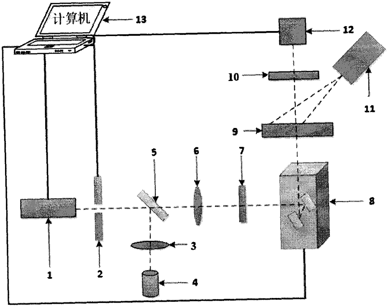
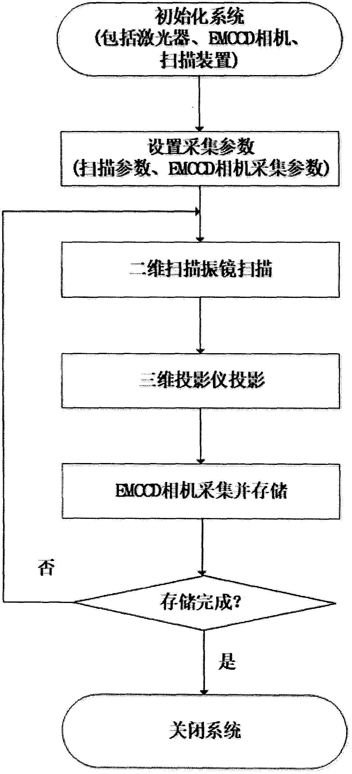
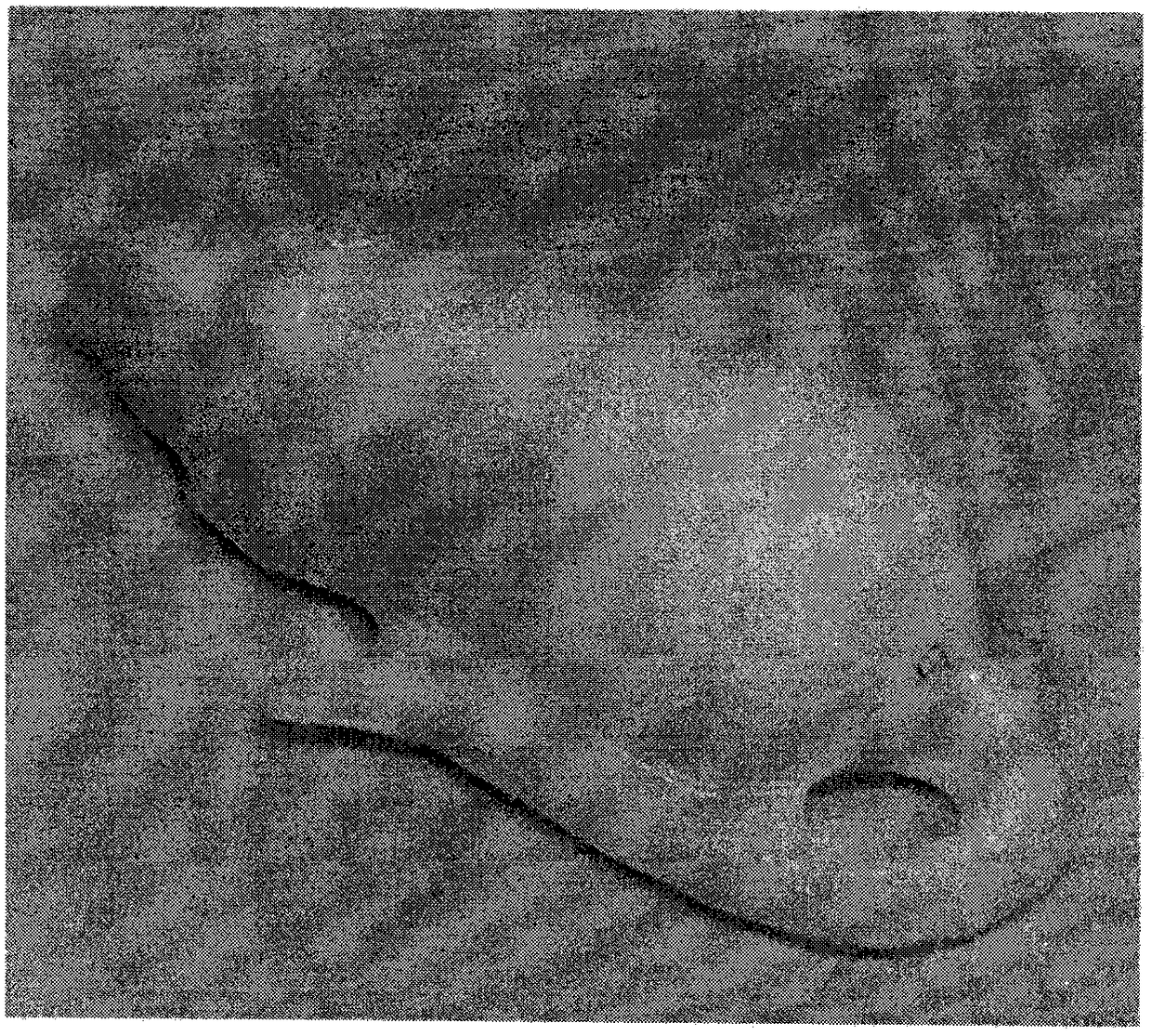

Image

  • Fluorescent molecular tomography system used in free space
  • Fluorescent molecular tomography system used in free space
  • Fluorescent molecular tomography system used in free space

Examples


specific Embodiment 1

[0027] Specific steps are as follows:

[0028] (1) Put the fluorescent tube with fluorescent dye into the abdominal cavity of the model mouse, such as image 3 As shown, put the model mouse on the platform so that the center of the model mouse body and the optical center of the lens of the EMCCD camera are in a straight line.

[0029] (2) Choose a 780nm long-wave pass filter and fix it in front of the EMCCD camera lens, adjust the angle of the three-dimensional projector, and project the model mouse.

[0030] (3) Open the control software in the computer, open the laser, the filter, the acquisition and scanning parameters of the EMCCD camera, etc. in the control software. After the parameter configuration is completed, click the start button of the control software to perform three-dimensional fluorescence measurement. The measured values ​​obtained are applied to Reconstruction, the obtained 3D reconstruction results are as follows Figure 4 shown.

specific Embodiment 2

[0031] Specific steps are as follows:

[0032] (1) Put the fluorescent tube with the fluorescent dye into the abdominal cavity of the nude mouse, and fix it on the platform, so that the center of the nude mouse body and the optical center of the lens of the EMCCD camera are in a straight line.

[0033] (2) Choose a 780nm long-pass filter and fix it in front of the lens of the EMCCD camera, adjust the angle of the three-dimensional projector, and project the nude mice.

[0034] (3) Open the control software in the computer, open the laser, the filter, the acquisition and scanning parameters of the EMCCD camera, etc. in the control software. After the parameter configuration is completed, click the start button of the control software to perform three-dimensional fluorescence measurement. The measured values ​​obtained are applied to Reconstruction, the obtained 3D reconstruction results are shown in Figure 5 shown.


PUM


Abstract

The invention provides a fluorescent molecular tomography system used in a free space. The fluorescent molecular tomography system comprises a laser device, an electric shutter, a semi-transparent semi-reflective mirror BS, a lens L1, a lens L2, a photodiode, a light filter F1, a light filter F2, a two-dimensional laser scanning galvanometer, a bearing table, a three-dimensional imaging projector,an EMCCD camera and a computer. The fluorescent molecular tomography system has the advantages of being compact, convenient to use and the like. The fluorescent molecular tomography system can achieve three-dimensional tomography of an examined body by controlling acquired data quantity and utilizing a reconstruction algorithm and accurately determine positions and strength fluorescence indicators.

Description

technical field [0001] The invention relates to the technical field of biomedicine, in particular to a fluorescent molecular tomographic imaging system in free space, which is suitable for early diagnosis of tumors. Background technique [0002] Fluorescence molecular tomography (FMT) is an emerging molecular imaging technology. Compared with the current breast imaging methods in clinical application, such as mammography, ultrasound imaging, and nuclear magnetic resonance, FMT has no It is widely used in breast tumor diagnosis, brain function detection and other fields due to its characteristics of damage, high sensitivity, high penetration and non-invasiveness. [0003] The early fluorescence molecular tomography system used the optical fiber contact measurement method after the animal was immersed in the matching liquid imaging cavity. In 2007, Deliolanis et al. of Harvard Medical School proposed a 360 non-contact fluorescent molecular tomography device for the first time...

Claims


Application Information

Patent Timeline
IPC IPC(8): A61B5/00
CPCA61B5/0064A61B5/0071A61B2503/40
Inventor 王慧泉冯杏赵喆王金海
Owner TIANJIN POLYTECHNIC UNIV
Learn More