
Workpiece surface treatment system and machining method thereof

A technology for processing system and workpiece surface, applied in processing models, decorative arts, engraving, etc., can solve the problems of waste of chips and materials, low efficiency of workpiece processing and detection, avoid waste of resources, ensure processing accuracy and consistency, realize The effect of recycling

Pending Publication Date: 2018-11-23
WUHU HUIYING AUTOMATIC EQUIP CO LTD
View PDF1 Cites 0 Cited by
  • Summary
  • Abstract
  • Description
  • Claims
  • Application Information

AI Technical Summary

Problems solved by technology

[0004] In order to solve the technical problems of low workpiece processing and detection efficiency and waste of chip materials existing in existing equipment, the present invention proposes a workpiece surface treatment system and its processing method

Method used


Image

  • Workpiece surface treatment system and machining method thereof
  • Workpiece surface treatment system and machining method thereof
  • Workpiece surface treatment system and machining method thereof

Examples


Embodiment 1

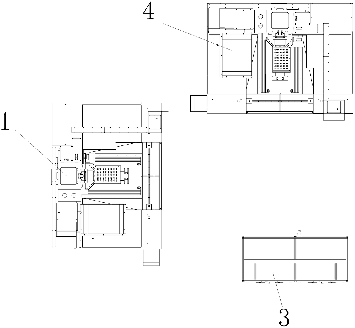
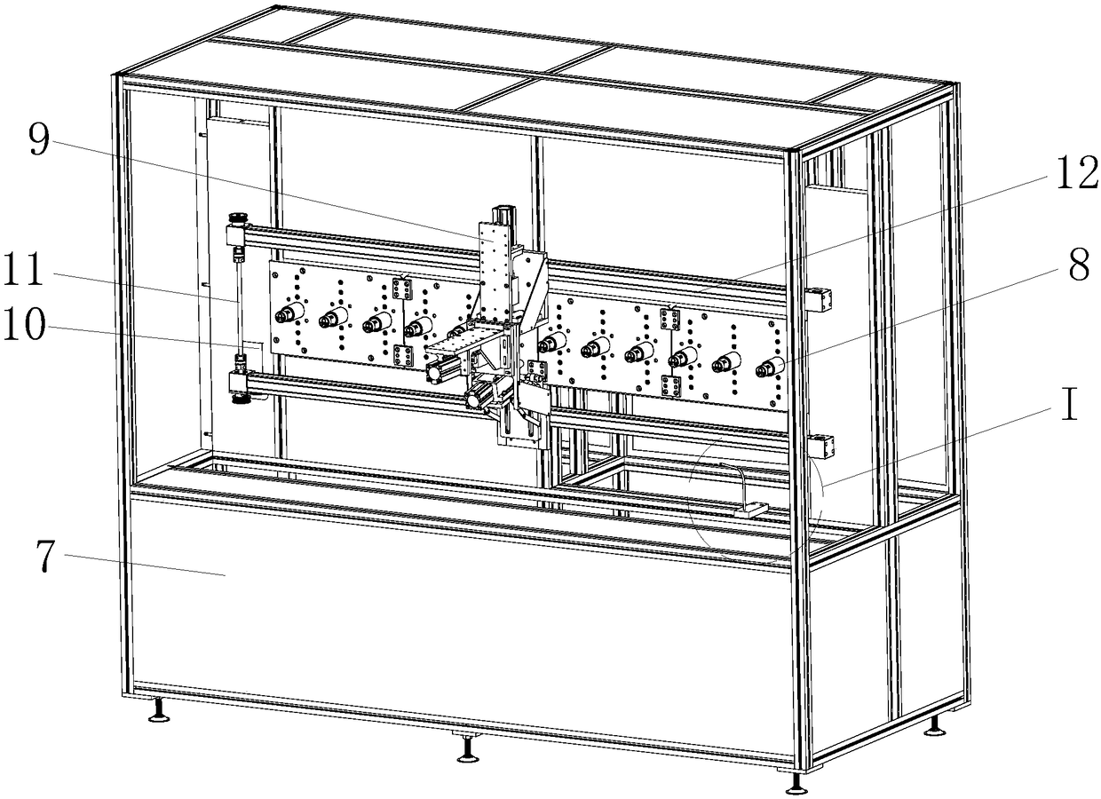
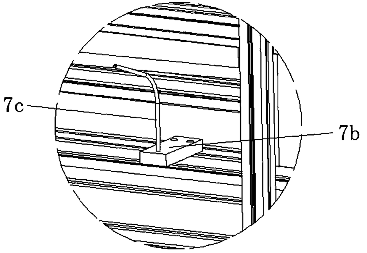
[0045] like Figure 1 to Figure 9 As shown, a workpiece surface treatment system includes:

[0046] at least one set of processing units;

[0047] The processing unit includes the following parts:

[0048] Machining center 1 is used to machine the workpiece;

[0049] The milling cutter engraving machine 4 is distributed on the side of the machining center and realizes further fine machining of the workpiece;

[0050] The processing unit also includes:

[0051] The airtightness test bench 3 is distributed on the side of the machining center 1 and has several test stations, any of which is used to receive the workpiece processed by the machining center 1 and automatically position and clamp it to perform the airtightness of the workpiece The performance test is performed, and then the clamping is released to output the workpiece, and the workpiece that passes the test enters the milling cutter engraving machine 4 for processing.

[0052] Each test station has a clamping and...

Embodiment 2

[0079] like figure 2 As shown, the second embodiment is realized on the basis of the first embodiment, that is, the processing unit is also distributed in the area surrounded by the processing center 1, milling cutter engraving machine 4, and air tightness test bench 3 And its grasping range covers the robot 2 in this area.

[0080] The robot is a six-axis robot, and there is a moving ground rail under the six-axis robot for reciprocating movement of the six-axis robot with a single degree of freedom.

[0081] A processing method of a workpiece surface treatment system, the steps of the method are as follows:

[0082] S1. Machining: the workpiece is placed in the machining center 1 for machining by means of robot pick-up;

[0083] S2. Air-tightness test: After the machining is completed, the machined workpiece is transported to the corresponding test station in the air-tightness test bench 3 by means of robot pick-up, and the lateral position of the workpiece is realized by...

Embodiment 3

[0088] like Figure 11 As shown, the third embodiment is realized on the basis of the first embodiment, that is, there is a material storage platform 5 for storing workpieces between the air tightness test platform and the machining center.

[0089] A processing method of a workpiece surface treatment system, the steps of the method are as follows:

[0090] S1. Machining: placing the workpiece stored on the storage table 5 in the machining center 1 for machining by manual pick-up;

[0091] S2. Air-tightness test: After the machining is completed, the machined workpiece is transported to the corresponding test station in the air-tightness test bench 3 by manual pick-up, and the lateral position of the workpiece is realized by clamping the positioning unit 8 . installed, the testing machine 9 can detect the airtightness of the workpiece on the station;

[0092] S3, engraving processing: when the number of workpieces that pass the test is the same as the number that can be proc...


PUM


Abstract

The invention relates to a workpiece surface treatment system and a machining method thereof. The system is provided with at least a set of machining unit; the set of the machining unit comprises thefollowing parts: a machining center and a milling cutter engraving machine, and further comprises an air impermeability test board, which is distributed on a side part of the machining center and provided with a plurality of test stations, any one test station is used for receiving and automatically locating and clamping workpieces treated by the machining center so as to perform air impermeability tests on the workpieces, then clamping is loosened to output the workpieces, and the workpieces, which are qualified upon tests, enter the milling cutter engraving machine to be machined. The systemis based on reasonable combination of machining equipment so as to constitute a whole set of complete machining system, and the machining accuracy and consistency of the workpieces are guaranteed; according to the workpiece surface treatment system, the horizontal clamping and detection mode of the workpieces is changed, an air impermeability test board is adopted to realize the side installationof the workpieces, on the one hand, the problem that chip powder is accumulated on the test stations to influence the installation and positioning of the workpieces is avoided, on the other hand, therecycle of the chip powder is realized, and the waste of resources is avoided.

Description

technical field [0001] The invention relates to the technical field of machining, in particular to a workpiece surface treatment system and a machining method thereof. Background technique [0002] In the field of machining, the surface processing of mechanical workpieces usually includes machining, sandblasting, wire drawing, electrophoresis, electroplating, spraying, grinding and other methods, and most of them are processed one by one for the workpieces. The processing equipment is relatively scattered and cannot A complete set of processing system is formed, which seriously affects the efficiency of the production and processing of workpieces, and the precision of the processed workpieces cannot be guaranteed to be uniform, so it is not suitable for batch production and processing. [0003] For example, the Chinese patent application number is 201410283672.8, and the patent name is a processing system and processing method for the surface of a workpiece. It is proposed t...

Claims


Application Information

Patent Timeline
Patent Type & Authority Applications(China)
IPC IPC(8): B44B1/00B44B1/06B44B3/00B44B3/06
CPCB44B1/00B44B1/06B44B3/00B44B3/06
Inventor 陈启岳
Owner WUHU HUIYING AUTOMATIC EQUIP CO LTD
Learn More