Oil tank truck cleaning treatment system and technology

A processing system and technology for oil tankers, applied in the field of oil tanker cleaning, can solve the problems of extensive management, low cleaning efficiency, consumption of large water resources, etc., achieve great environmental and social benefits, reduce cleaning costs, and improve economic benefits. Effect

Pending Publication Date: 2018-12-07
SHANDONG TIANLI DRYING TECH & EQUIP
View PDF11 Cites 11 Cited by
  • Summary
  • Abstract
  • Description
  • Claims
  • Application Information

AI Technical Summary

Problems solved by technology

Each has different disadvantages: 1) The manual cleaning process not only has low cleaning efficiency, high labor intensity, and poor cleaning quality, but also has great harm to the health of cleaning personnel
At the same time, corresponding boiler rooms need to be built, and the investment in supporting equipment and facilities is huge.
The volatilized oil vapor pollutes the surrounding environment more seriously, and the working conditions of the workers are poor
Moreover, the cleaning work can only be carried out at a fixed tank washing station, which has relatively large limitations. The tank washing efficiency is low and the cost and energy consumption are high; Cause environmental pollution, and, in order to prevent the chemicals in cleaning from causing corrosion damage to the tank wall, it is necessary to use appropriate corrosion inhibitors to protect the cleaned equipment during cleaning
At the same time, removing the residual chemical solution attached to the tank wall not only requires a large amount of clean water, but the residual chemical components may also have a certain impact on the quality of the stored oil.
4) High-pressure water jet cleaning technology has been widely used in the cleaning of foreign railway tank cars. However, the investment in building a fixed tank washing station is huge, and it is only suitable for occasions where a large number of tank cars are cleaned, such as large oil refineries and tank washing stations.
Jet cleaning generally uses cold water as the working medium, which cannot work in winter in northern regions
At the same time, jet flushing not only consumes a lot of water resources, but also costs a lot for the recovery and treatment of oily wastewater after tank washing
Not only that, the high-pressure water cleaning process is also easy to destroy the protective layer formed on the inner wall of the tank car, and the use of high-pressure working medium is prone to accidents, and the one-time investment and maintenance costs are high
[0003] In short, the above cleaning methods for tank trucks currently used in my country are not ideal. The traditional tank truck cleaning technology with high energy consumption, low efficiency and high pollution is facing severe challenges, and there is an urgent need to develop and apply new economical and environmentally friendly technical solutions. for tank truck cleaning
Furthermore, the cleaning of traditional road tank trucks is mostly self-operated by retail investors, with small scale, backward facilities, and extensive management. On the one hand, it causes a great waste of water resources; on the other hand, the wastewater and waste gas generated during the cleaning process have not been treated. It is directly discharged into the environment, causing very serious environmental problems; in addition, the extensive management and backward cleaning technology make the cleaning quality unable to guarantee, causing the next batch of oil pollution or welding quality accidents

Method used


Image

  • Oil tank truck cleaning treatment system and technology
  • Oil tank truck cleaning treatment system and technology
  • Oil tank truck cleaning treatment system and technology

Examples


Embodiment Construction

[0037] The technical solutions of the present invention will be further described below in conjunction with the accompanying drawings and embodiments.

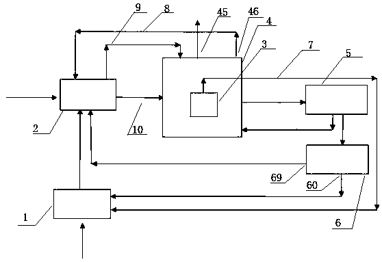
[0038] figure 1 Among them, an oil tanker cleaning treatment system includes a boiler device 1, a cleaning device 2, an exhaust gas treatment device 4, a waste heat recovery device 5, and a sewage treatment device 6 connected in sequence; the boiler device 1 is connected to the cleaning device 2, which is a cleaning device 2 to provide low-pressure steam; the exhaust gas generated by the cleaning device 2 enters the exhaust gas treatment device 4.

[0039] Boiler device 1 includes a boiler main unit, boiler supporting auxiliary machines, and boiler supporting instrument valves. The boiler main unit is a horizontal gas-fired steam boiler; the boiler unit generates low-pressure steam.

[0040] The cleaning device 2 includes a manhole cover, a quick connection of the discharge port, a spray gun, a rubber hose, a water pressure t...


PUM


Abstract

The invention discloses an oil tank truck cleaning treatment system and technology. The system comprises a boiler device, a cleaning device, an oil vapor trap device, a waste gas treatment device, a waste heat recycling device and a sewage treatment device. The boiler device is connected with the cleaning device, the oil vapor trap device is located in the middle of a spraying tower of the waste gas treatment deice, one part of waste liquid of the spraying tower is returned into the spraying tower through a circulation pump, the rest enters the sewage treatment device, and unabsorbed oil vaporenters the boiler deice through the top of the oil vapor trap device for secondary air combustion. The low-pressure vapor tank technology most advanced in China is adopted, the cleaning quality is ensured, scale cleaning is achieved, more than 200 oil tank trucks are treated daily, the efficiency can be greatly improved compared with retail investor extensive type cleaning, consumption of low-pressure steam amount of each truck is reduced by 55% or more, cleaning sewage is recycled after being treated, the cleaning cost of each truck is reduced, and economic benefits are improved. Waste gas is exhausted after being treated and reaching standards, no pollution is caused to surrounding, and great environmental and social benefits are produced.

Description

technical field [0001] The invention relates to the technical field of oil tank car cleaning, in particular to an oil tank car cleaning treatment system and process. Background technique [0002] Oil tanker is an important tool for storing and transporting oil products. It is widely used in my country's industry, military, economic and other fields, and its number is increasing year by year. In order to ensure the safety and quality of oil transportation, the inner wall of the tanker must be cleaned and repaired regularly . The current tank car cleaning process operation methods in my country can be roughly divided into the following types: (1) Manual cleaning method. (2) High temperature steam washing method. (3) Soak and clean with chemical liquid. (4) High pressure water cleaning technology. Each has different disadvantages: 1) The manual cleaning process not only has low cleaning efficiency, high labor intensity, and poor cleaning quality, but also has great harm to t...

Claims


Application Information

Patent Timeline
Patent Type & Authority Applications(China)
IPC IPC(8): B08B9/093B60P3/22B01D47/06B01D53/00B01D53/04C02F9/00
CPCB01D47/06B01D53/002B01D53/04C02F9/00B08B9/093B60P3/22C02F1/001C02F1/40C02F1/24C02F1/44C02F1/52B01D2253/102
Inventor 柴本银尹凤交王寿权张自督耿文广刘金勇
Owner SHANDONG TIANLI DRYING TECH & EQUIP
Why Eureka
Try Eureka