A single-grid slow-wave structure with a curved profile

A technology of slow-wave structure and curved profile, which is applied to the circuit components of transit-time electronic tubes, can solve the problems of low injection-wave interaction efficiency and difficulty in increasing output power, and achieve weak injection-wave interaction and improved distribution Inhomogeneity, effect of improving electron interaction efficiency and output power

Inactive Publication Date: 2018-12-11
SHENZHEN UNIV
View PDF2 Cites 3 Cited by
  • Summary
  • Abstract
  • Description
  • Claims
  • Application Information

AI Technical Summary

Problems solved by technology

The above characteristics make vacuum electronic devices based on this slow wave structure have...

Method used


Image

  • A single-grid slow-wave structure with a curved profile
  • A single-grid slow-wave structure with a curved profile
  • A single-grid slow-wave structure with a curved profile

Examples


Embodiment 1

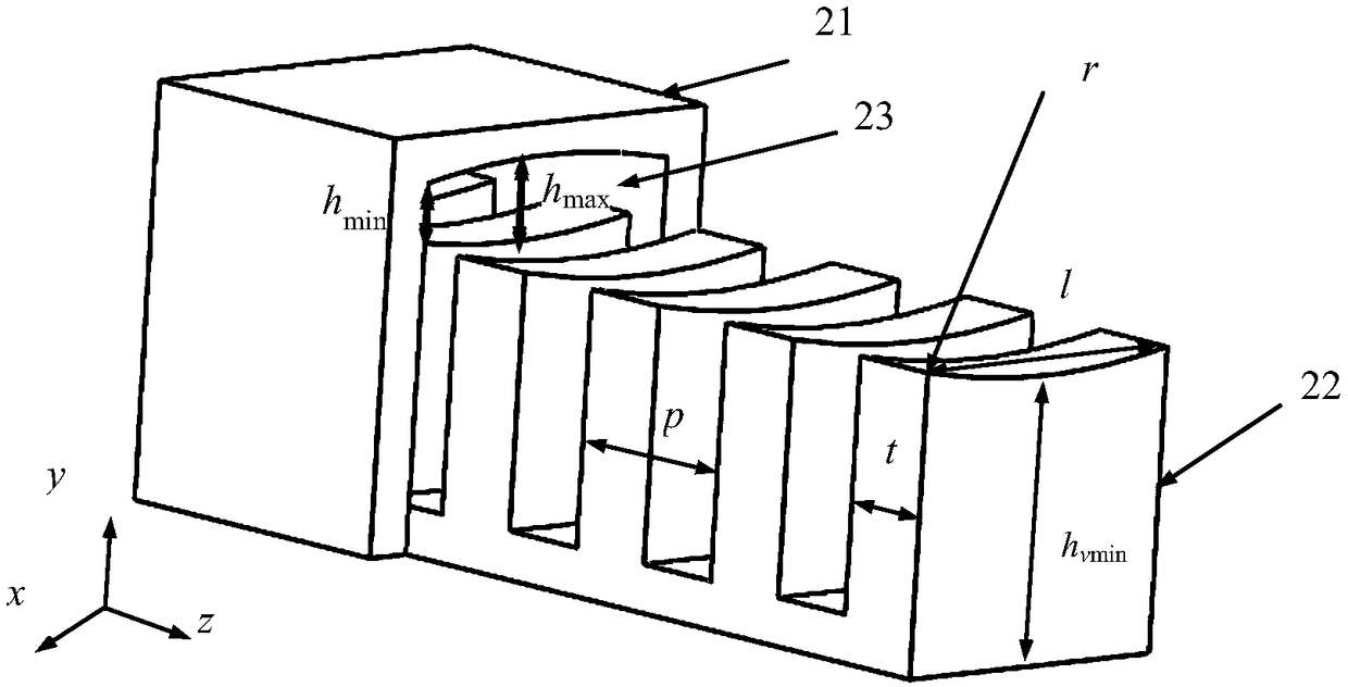
[0033] In this embodiment, an arc-profile single-grid slow-wave structure working in the Q-band is taken as an example. Such as figure 2 As shown, it includes a cuboid housing 21, grid teeth 22 and strip-shaped electron injection channel 23. The two broad side contours of the electron injection channel 23 are a section of arc, the radius r of the arc is 22.1 mm, and the chord length l is 4.2 mm. . The maximum height h of the electron injection channel 23 in the vertical direction max is 0.7mm. The minimum height of the grid teeth is hv min It is 1.45mm, and its thickness t is 1.5mm. The pitch p between the grid teeth is 3 mm.

[0034] Figure 5 , Image 6 with Figure 7 The dispersion characteristic curves, average coupling impedance characteristic curves, and the growth rate of coupling impedance changing curves with the broadside direction of the traditional straight line profile and the new circular arc profile single-grid slow-wave structure provided by this embod...

Embodiment 2

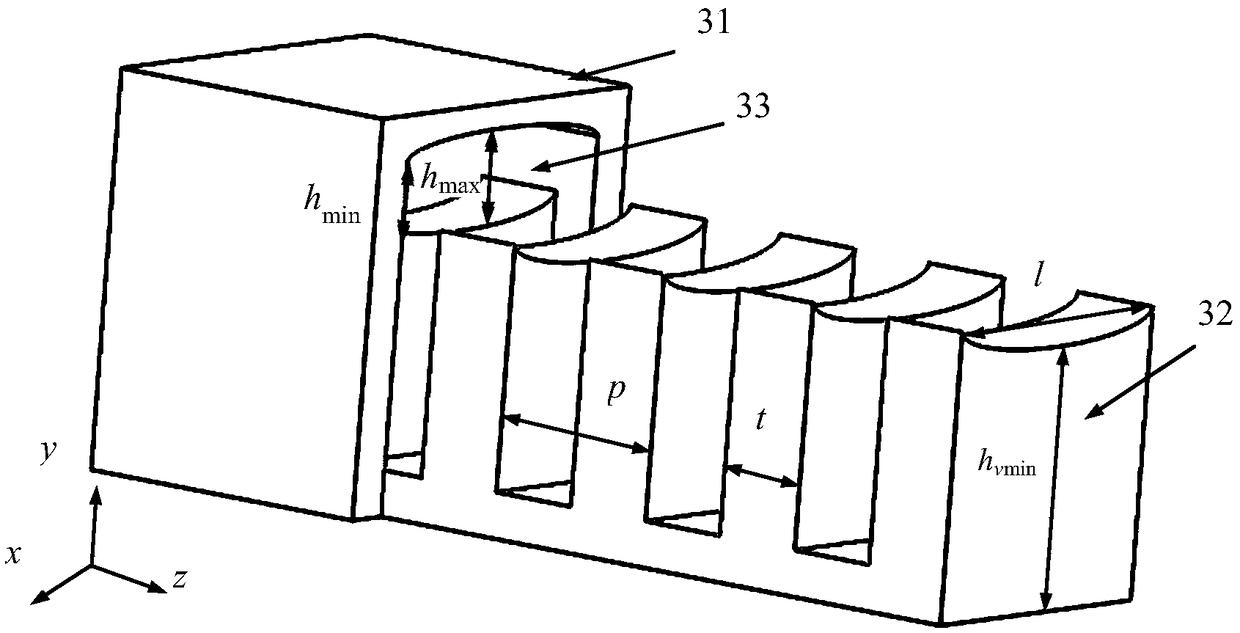
[0036] In this embodiment, the curve profile of the sinusoidal function distribution working in the Q band is taken as an example. Such as image 3 As shown, it includes a cuboid housing 31, grid teeth 32 and strip-shaped electron injection channel 33. The two broadside profiles of the electron injection channel are curved profiles distributed with a sinusoidal function. Wherein, the peak value of the sine function is 0.45 mm, and the cycle length is 16.8 mm. Take a curve profile of the sinusoidal function curve at π / 4 to 3π / 4, and the corresponding chord length l is 4.2mm. The maximum height h of the electron beam channel in the vertical direction max 0.9mm, minimum height h min 0.5mm. The minimum height of the rectangular grid teeth is hv min It is 1.45mm, and its thickness t is 1.5mm. The pitch p between the grid teeth is 3 mm.

[0037] Figure 8 , Figure 9 with Figure 10 The dispersion characteristic curves, average coupling impedance characteristic curves, and...


PUM

PropertyMeasurementUnit
Thicknessaaaaaaaaaa

Abstract

The invention discloses a single-grid slow-wave structure with a curved profile, which is composed of a rectangular solid shell, grid teeth distributed along the longitudinal direction in periodicallyand electron beam channels with curved contour. The slow-wave structure can improve the average coupling impedance, the uniformity of the coupling impedance in the wide-side direction and the intensity of the beam-wave interaction without changing the dispersion characteristics of the slow-wave structure, so that the electron interaction efficiency and the output power of the traveling wave tube/backward wave tube based on the slow-wave structure can be improved. For the TWT, the gain of the whole TWT can also be improved. The millimeter-wave terahertz traveling wave tube/backward wave tube based on this slow-wave structure has many advantages, such as compact structure, high electronic efficiency, high output power and so on. The structure will be widely used in aspects such as high datarate communication systems, high precision imaging systems, electronic countermeasure systems and radar complete appliance systems.

Description

[technical field] [0001] The invention belongs to the technical field of microwave vacuum electronics, and in particular relates to a single-grid slow-wave structure with a curved profile. [Background technique] [0002] Due to the characteristics of short wavelength, high frequency, low photon energy, high signal-to-noise ratio, and extremely wide bandwidth, millimeter wave / terahertz wave is used in many military and civilian applications such as security imaging, nondestructive testing, biomedicine, high data rate communication, and radar detection. The field has broad application prospects. Millimeter wave source / terahertz source is the basis of millimeter wave / terahertz technology and an indispensable device in millimeter wave / terahertz application system, and the millimeter wave terahertz source based on vacuum electronics is the current research on millimeter wave terahertz source an important branch of the field. In vacuum electronic devices, ribbon-shaped injection...

Claims


Application Information

Patent Timeline
IPC IPC(8): H01J23/24
Inventor 舒国响钱正芳熊浩孙一翎范姝婷陈乐戴翔宇周灿钦梁豪
Owner SHENZHEN UNIV
Why Eureka
Try Eureka