

Indoor quantitative performance detection system for radar emitting slave laser
A technology of laser radar and quantitative detection, applied in the direction of radio wave measurement system, instrument, etc., to achieve the effect of good quantification, high stability and simple operation
- Summary
- Abstract
- Description
- Claims
- Application Information
AI Technical Summary
Problems solved by technology
Method used
Image

Examples
Embodiment approach
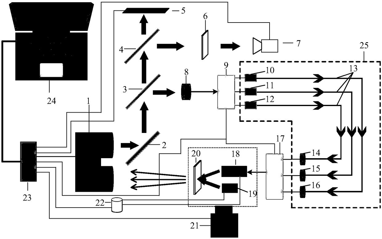
[0009] As a specific implementation manner, the full-transmission mirror 2 is at an angle of 45° to the transmission system of the laser radar 1 .
specific Embodiment approach
[0010] As a specific implementation manner, the total reflection mirror 2 , the first beam splitter 3 and the second beam splitter 4 are parallel to each other.
[0011] As a specific implementation manner, the transmission screen 6 is parallel to the mechanical axis of the transmitting system of the laser radar 1 .
[0012] As a specific implementation, the CCD camera 7 is facing the transmission screen 6 .
[0013] As a specific implementation, the laser echo and background light characteristic database 22 provides laser echo signals and background light noise signals under specific conditions, the specific conditions include different target reflectivity, sunlight illumination and other conditions.
[0014] As a specific implementation manner, the lengths of the optical fibers 13 in the multi-distance optical fiber delay assembly 25 are all different.
[0015] The specific work process of the system of the present invention is as follows:
[0016] The laser light emitted ...
Embodiment 1
[0022] In order to verify the effectiveness of the system of the present invention, the following detection system is set up in this embodiment. The tested lidar 1 is a binocular lidar with a wavelength of 905nm and a frequency of 10KHz; the total reflection mirror 2 is a 905nm total reflection mirror; the splitting ratio of the beam splitters 3 and 4 is 4:1; the optical power detector is LaserPoint’s PD50-D9-VIS photoelectric power meter; transmission screen 6 and simulated target 20 are translucent black acrylic plates; CCD camera 7 model is MTV-1881EH; optical receivers 8, 14, 15, and 16 use detectors from Beijing Minguang Technology Co., Ltd.'s 0.5mm Fast Silicon PIN photodiode; distance gating switches 9 and 17 are implemented by EPCS1N series FPGA programmable devices; the lasers used for optical transmitters 10, 11, 12 and program-controlled laser echo sources are Hamamatsu's L11854-307- 05 pulsed laser diodes; the optical fiber 13 is a 9 / 125 single-mode optical fiber; ...
PUM
 Abstract
Description
Claims
Application Information