Collecting system for printing and coating waste gas

A technology for collecting system and waste gas, applied in gas treatment, lighting and heating equipment, chemical instruments and methods, etc., can solve the problems of large-scale treatment equipment, high operating cost, large energy consumption, etc., and achieve low operating cost and thermal energy saving. , the effect of reducing the air volume

Inactive Publication Date: 2018-12-21
青岛大拇指环境工程有限公司
View PDF6 Cites 2 Cited by
  • Summary
  • Abstract
  • Description
  • Claims
  • Application Information

AI Technical Summary

Problems solved by technology

In recent years, some of the newly manufactured and installed printing machines have carried out simple internal circulation and partially recycled the heat. However, due to the large air volume, the energy consumption during heating is huge, and the air volume is large. The treatment used for exhaust gas treatment The scale of the equipment is large, and the operating cost is also high

Method used


Image

  • Collecting system for printing and coating waste gas

Examples


Embodiment approach

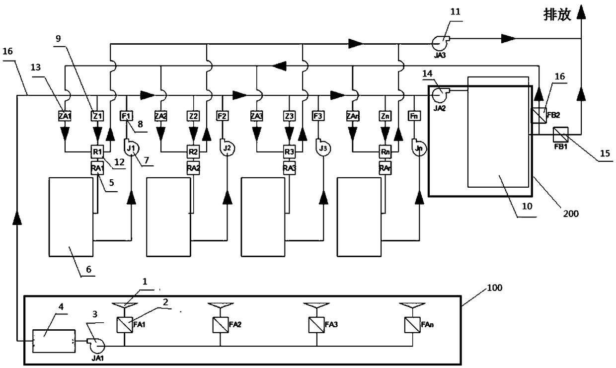
[0027] As a preferred embodiment of the present invention, the fresh air intake system 100: includes a suction port 1, a fresh air blower 3 and a filter 41 which are sequentially connected by pipelines, and the suction port 1 is provided with a fresh air regulating valve 2, The outlet of the filter 41 is connected with the inlet of the hot air drying system.

[0028] As a preferred embodiment of the present invention, the hot air drying system includes an electric heater 5 and a hot air drying fan 7, the electric heater 5 is connected to the outlet of the filter 41 through a pipeline, and the electric heating The inlet of the device 5 is provided with an air volume regulating valve 9; the electric heater 5, the printing machine 62, and the hot air drying fan 7 are connected in sequence, and the outlet of the hot air drying fan 7 is connected with the inlet of the tail gas treatment system 200 and set There is a check valve 8; wherein, the outlet of the heat recovery system is ...

Embodiment 1

[0035] Such as figure 1 As shown, in the figure FA1, FA2, FA3, FAn represent several fresh air regulating valves 2; Z1, Z2, Z3, Zn represent several air volume regulating valves 9; RA1, RA2, RA3, RAn represent several electric heaters 5; R1, R2, R3, Rn represent several heat exchangers 12; ZA1, ZA2, ZA3, ZAn represent several recycling regulating valves 13; JA1 represents fresh air fan 3; JA2 represents exhaust fan 14; JA3 represents exhaust fan; J1, J2, J3, Jn represent several hot air drying fans 7; FB1 represents the discharge valve 15; FB2 represents the regulating valve 16;

[0036] This embodiment is a collection system for printing and coating waste gas. A printing waste gas collection system and treatment method include:

[0037] Fresh air intake system 100, hot air drying system, tail gas treatment system 200, heat recovery system.

[0038] The fresh air intake system 100 includes four parallel suction inlets 1 , four parallel suction branch pipelines, a fresh air r...


PUM


Abstract

The invention relates to a collecting system for printing and coating waste gas. The collecting system comprises a fresh air intake system, a hot air drying system, a printing machine and a tail gas treatment system which are sequentially connected, wherein the tail gas treatment system is connected with the hot air drying system through a heat energy recycling system; the fresh air sucked by thefresh air intake system is sent into the printing machine via the hot air drying system, and carries the waste gas in the printing machine out of the tail gas treatment system; the high-temperature waste gas treated by the tail gas treatment system is performed with heat exchange by the heat energy recycling system, and the gas after heat exchange is exhausted out; the heat absorbed by the heat energy recycling device is recycled into the hot air drying system. The collecting system has the advantages that part or all of heat energy can be recycled by the heat energy recycling system; the hotair is directly recycled to a circulating drying air inlet of the printing machine by the hot air recycling system, so as to greatly reduce the air volume and fully recycle the heat energy; the running cost of tail gas treatment is greatly reduced, a large amount of heat energy is saved, and the higher social and economic benefits are realized.

Description

technical field [0001] The invention relates to the field of VOCs waste gas treatment, in particular to a collection system for printing and coating waste gas. Background technique [0002] VOCs are a class of volatile organic compounds with a boiling point lower than 250°C, which are very harmful to human health and the ecological environment. Effective treatment of this type of organic waste gas can not only avoid environmental pollution, but also reduce the operating costs of enterprises, and have high social and economic benefits. [0003] In the printing industry, a large amount of VOCS-containing exhaust gas is also emitted, especially in the color printing process. Due to the need for overprinting, that is, after printing one color, it needs to be dried quickly in order to print the next color. In the existing printing presses, the surrounding air is generally directly extracted, heated and then entered into the drying box of the printing press, and then discharged. ...

Claims


Application Information

Patent Timeline
Patent Type & Authority Applications(China)
IPC IPC(8): B01D46/00B01D53/26F23G7/06
CPCB01D46/00B01D53/26B01D2257/708F23G7/06
Inventor 陈琴波陈青松张文智贺国臣钟适谦姚俊朝
Owner 青岛大拇指环境工程有限公司
Why Eureka
Try Eureka