An ion source that reduces the rate of electron escape

A technology of escape rate and ion source, which is applied in the field of ion sources that can reduce the escape rate of electrons, and can solve problems such as increasing the etching of cathode magnetic pole pieces, affecting the quality of coating, and electron escape.

Active Publication Date: 2018-12-21
成都极星等离子科技有限公司
View PDF6 Cites 11 Cited by
  • Summary
  • Abstract
  • Description
  • Claims
  • Application Information

AI Technical Summary

Problems solved by technology

[0005] Existing ion sources are simply designed with permanent magnets or electromagnets on one side of the cathode magnetic circuit, which will lead to asymmetrical distribution of the magnetic field at the gap of the cathode magnetic pole piece, so that electrons are in the runway of the orthogonal electromagnetic field. When drifting upward, the constraints on the inner and outer sides are asymmetrical, and it is easy for most of the elect

Method used


Image

  • An ion source that reduces the rate of electron escape
  • An ion source that reduces the rate of electron escape

Examples


Embodiment Construction

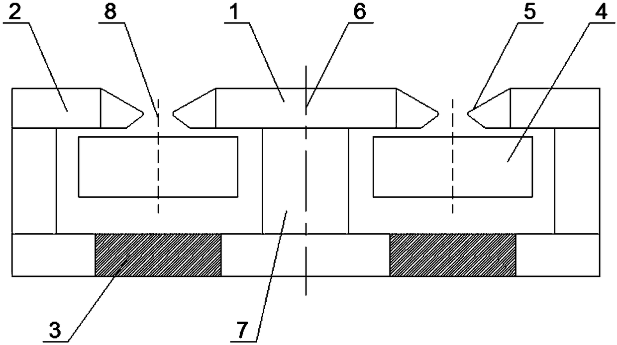
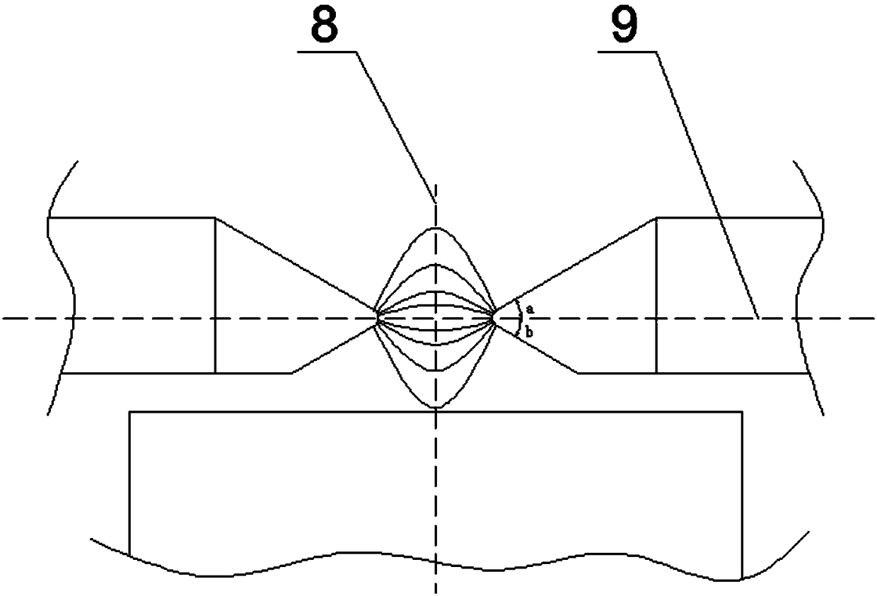
[0018] Such as figure 1 and figure 2 As shown, the ion source that can reduce the escape rate of electrons provided by this embodiment includes a discharge chamber composed of an anode ring 4, an inner cathode 1 and an outer cathode 2, and the anode ring 4 is located between the inner cathode 1 and the outer cathode 2, The anode ring 4, the inner cathode 1 and the outer cathode 2 are all axisymmetric structures, and the entire discharge chamber is symmetrical about the central axis 6. Specifically, a soft magnetic column 7 is fixed in the middle of the yoke of the outer cathode 2, and the soft magnetic One end of the column 7 passes through the center of the inner hole of the anode ring 4 and is connected to the middle part of the inner cathode 1, and the yoke of the outer cathode 2 is provided with two permanent magnets 3, which are symmetrical about the soft magnetic column 7, By adding a permanent magnet 3, two independent magnetic circuits can be formed in the whole ion ...


PUM

PropertyMeasurementUnit
Radiusaaaaaaaaaa

Abstract

The invention discloses an ion source capable of reducing an electron escape rate, including an anode ring, inner cathode and outer cathode, the anode ring, the inner cathode and the outer cathode areeach axisymmetric, a soft magnetic column is fixed in the middle of the yoke of the outer cathode, one end of the soft magnetic column passes through the center of the inn hole of the anode ring andis connected with the middle of the inner cathode, the longitudinal cross-sectional shape of the magnetic pole shoe of the inner cathode is mirror symmetrical with the longitudinal cross-sectional shape of the magnetic pole shoe of the outer cathode of the corresponding position, and an annular cathode gap is formed between the magnetic pole shoe of the inner cathode and the magnetic pole shoe ofthe outer cathode, the anode ring is directly opposite to the lower part of the cathode gap, two permanent magnets are arranged on the magnetic yoke of the outer cathode, the two permanent magnets aresymmetrical with respect to the soft magnetic column, and the two permanent magnets are respectively positioned directly below the opposite sides of the anode ring. By increasing the symmetrical magnetic field, the invention improves the uniformity of the magnetic field distribution on both sides of the cathode gap, can reduce the escape rate of electrons and effectively reduce the bombardment probability of the electrons on the cathode magnetic pole shoe.

Description

technical field [0001] The invention relates to the technical field of ion source equipment, in particular to an ion source capable of reducing the escape rate of electrons. Background technique [0002] An anode layer plasma source is usually used in the PECVD (Plasma Enhanced Chemical Vapor Deposition) reaction. In the DLC deposition process, it is used to ionize inert gases such as argon, or directly ionize acetylene, acetone, etc. The deposition gas makes it form an ion flow and injects it into the reaction vacuum chamber, and increases the ionization rate of the deposition reaction gas, thereby increasing the proportion of SP3 in the DLC coating and the deposition rate, so as to improve the quality of the deposited film and the deposition time shortening. [0003] The anode layer ion source was originally developed from a closed drift ion thruster used in space engines. An annular gap is opened on the cathode plate, an annular anode is set under the annular gap, and a ...

Claims


Application Information

Patent Timeline
IPC IPC(8): H01J27/14
CPCH01J27/143
Inventor 王鸣陈刚
Owner 成都极星等离子科技有限公司
Why Eureka
Try Eureka