
Sintering flue gas dedusting and denitration integrated process

A technology of sintering flue gas and denitrification, applied in the direction of gas treatment, improvement of process efficiency, chemical instruments and methods, etc., can solve problems such as shortening process flow, and achieve the effect of saving sealing investment

Active Publication Date: 2018-12-25
武汉钢铁有限公司
View PDF6 Cites 13 Cited by
  • Summary
  • Abstract
  • Description
  • Claims
  • Application Information

AI Technical Summary

Problems solved by technology

[0010] In addition, in the flue gas in different areas of the sintering machine, SO 2 There are also large differences in the concentration, such as low flue gas temperature in the low temperature flue gas area, SO 2 The concentration is also low, high temperature flue gas area, SO 2 The concentration is too high, how to effectively deal with the flue gas with different amounts of pollution in different periods of the sintering process, minimize the impact of flue gas discharge on the environment, effectively recover waste heat, shorten the process flow, reduce investment costs and equipment footprint, Improving the treatment efficiency of desulfurization and denitrification is a problem that researchers need to solve

Method used


Image

  • Sintering flue gas dedusting and denitration integrated process
  • Sintering flue gas dedusting and denitration integrated process
  • Sintering flue gas dedusting and denitration integrated process

Examples


Embodiment Construction

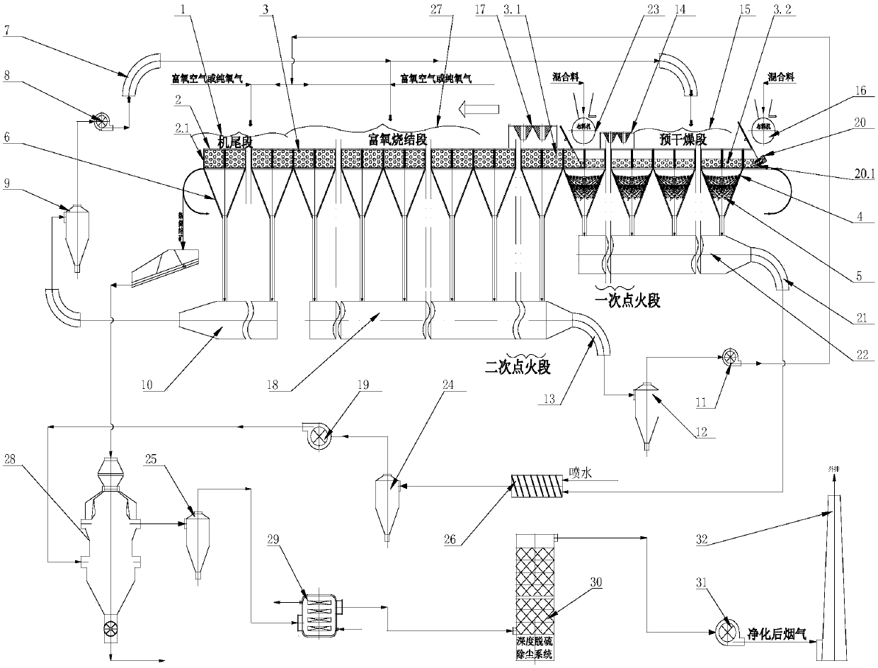
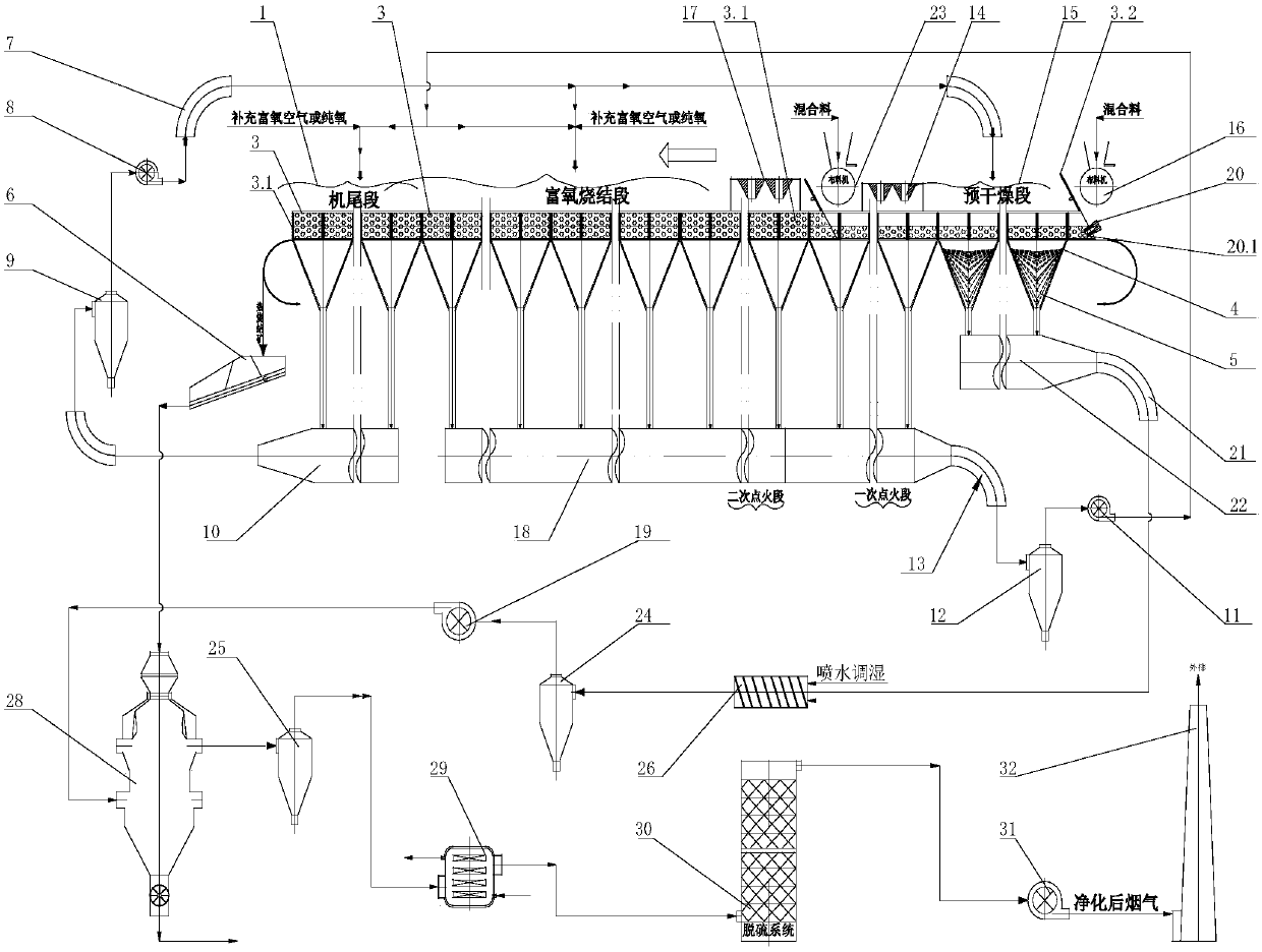
[0038] see figure 1 , the system used for the process of the present invention includes a sintering machine 2, a bellows 6 is provided under the trolley 2.1 of the sintering machine 2, and the sintering machine is successively divided into a pre-drying section, an ignition section, and an oxygen-enriched sintering section along the traveling direction of the trolley and 4 regions of the tail section, wherein the ignition section includes a primary ignition section provided with a primary ignition system 14 and a secondary ignition section of a secondary ignition system 17; , A secondary cloth assembly 23 is arranged above the end of the primary ignition section.

[0039] The wind box 6 below the tail section is connected to the high-temperature circulation above the preheating drying section through the high-temperature flue gas main flue 10, the high-temperature flue gas dust collector 9, the high-temperature flue gas circulation fan 8 and the high-temperature flue gas circul...


PUM

PropertyMeasurementUnit
Diameteraaaaaaaaaa
Thicknessaaaaaaaaaa
Diameteraaaaaaaaaa

Abstract

The invention discloses a sintering flue gas dedusting and denitration integrated process. The technical scheme includes that a sintering machine comprises four areas including a pre-drying section, an ignition section, a rich-oxygen sintering section and a tail section sequentially arranged along a moving direction of a trolley; sintering flue gas of the pre-drying section is collected by a corresponding lower air chamber, sent into a main low-temperature flue, guided out through a low-temperature flue gas pipe, a first low-temperature flue gas deduster, a low-temperature flue gas circulationfan and a main exhaust fan and sent into a sinter cooling furnace to realize heat exchange denitration with hot sinter, and sintering flue gas heated in heat exchange is subjected to dedusting through a second low-temperature flue gas deduster and heat recovery through a waste heat boiler, then sent into a desulfurization system for desulfurization and further purified prior to being exhausted; the side wall of the corresponding lower air chamber of the pre-drying section is peripherally provided with at least one layer of liquid ammonia nozzles, and excessive liquid ammonia or ammonium hydroxide is sprayed into sintering flue gas in the air chamber through the nozzles. The process is simple, low equipment investment and operating cost are realized, sintering flue gas is recycled based onquality, and online flue gas desulfurization and denitration can be realized.

Description

technical field [0001] The invention relates to the field of environmental protection, in particular to an integrated process for dust removal and denitrification of sintering flue gas. Background technique [0002] The sintering process is an important emission source of gaseous pollutants in the iron and steel production process. Currently, the commonly used pollutant removal technologies mainly focus on the terminal treatment outside the sintering system. In the combined process of SDA desulfurization + SCR denitrification, in order to reduce the input of SCR denitrification and reduce the cost of denitrification, the development of low-cost, long-life and high-efficiency catalysts has become a current research hotspot. [0003] Iron-based oxide catalysts have the advantages of high nitrogen selectivity, low cost, and wide sources. Many researchers are interested in NO X Transformation performance was discussed in detail. [0004] Kato et al. 2 Fe was prepared as a car...

Claims


Application Information

Patent Timeline
IPC IPC(8): B01D53/75B01D53/78B01D53/56B01D53/90B01D53/50B01D50/00B01D46/00F27D17/00F27D13/00F27B21/08
CPCB01D46/00B01D50/00B01D53/502B01D53/75B01D53/78B01D53/8628B01D53/90B01D2255/20738B01D2257/302B01D2257/404B01D2258/0283F27B21/00F27D13/00F27D17/00F27D17/004F27D2017/006Y02P10/25
Inventor 吴高明李富智付本全汤静芳卢丽君
Owner 武汉钢铁有限公司
Learn More