Device and method for removing nitrogen and carbon from sewage with high ammonia-nitrogen content and low carbon-nitrogen ratio

A technology with low carbon-to-nitrogen ratio and high ammonia-nitrogen, applied in chemical instruments and methods, water/sewage treatment, water/sewage multi-stage treatment, etc., can solve the problem that nitrate nitrogen cannot meet the discharge standard, and achieve biochemical stability , avoid competition, wide-ranging effects

Pending Publication Date: 2018-12-28
北京安国水道自控工程技术有限公司
View PDF0 Cites 4 Cited by
  • Summary
  • Abstract
  • Description
  • Claims
  • Application Information

AI Technical Summary

Problems solved by technology

However, for high ammonia nitrogen sewage, the nitrate nitrogen produced by ...

Method used


Image

  • Device and method for removing nitrogen and carbon from sewage with high ammonia-nitrogen content and low carbon-nitrogen ratio

Examples


Embodiment 1

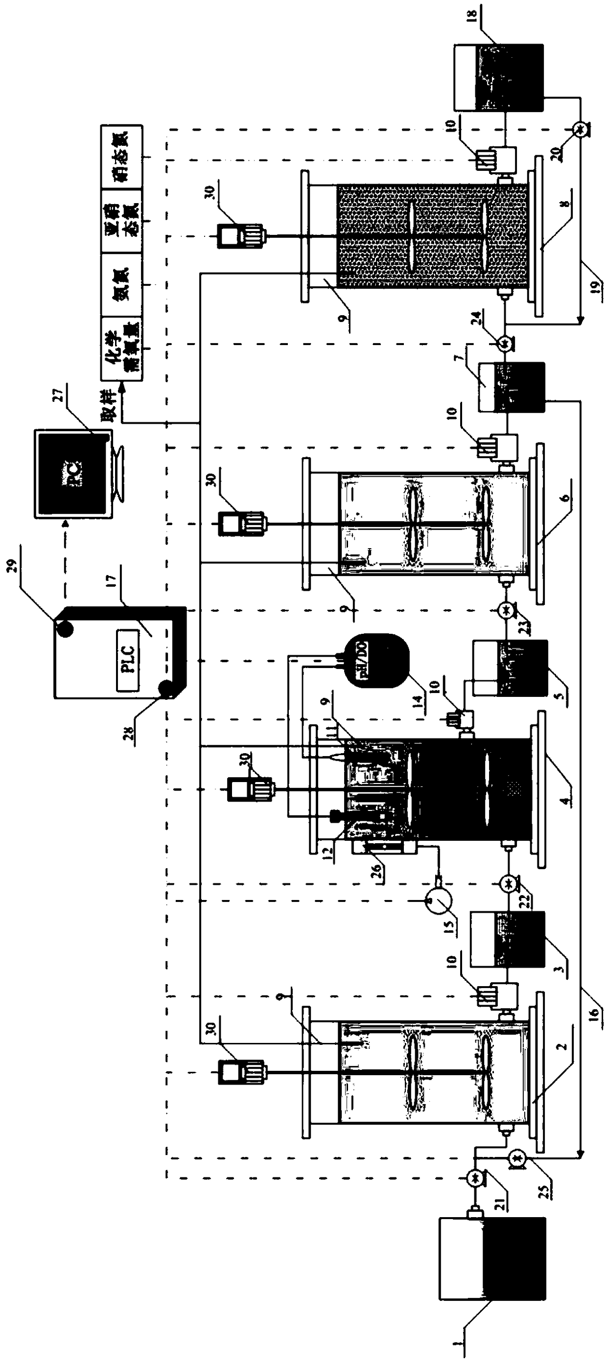
[0104] The denitrification and carbon removal device for high ammonia nitrogen and low carbon nitrogen ratio sewage is as follows: figure 1 shown, including

[0105] Raw water tank 1, denitrification carbon removal S reactor 2, intermediate water tank after carbon removal 3, partial short-range nitrification reactor 4, intermediate water tank after nitrification 5, anaerobic ammonium oxidation reactor 6, intermediate water tank after ammonia oxidation, which are connected in sequence through pipelines Water tank 7, ion exchange resin reactor 8 and water outlet tank 18;

[0106] The denitrification carbon removal SBR reactor 2, the partial short-path nitrification SBR reactor 4, the anammox SBR reactor 6 and the ion exchange resin SBR reactor 8 all use SBR reactors;

[0107] The interior of the denitrification carbon removal reactor 2, part of the short-range nitrification reactor 4, the anammox reactor 6 and the ion exchange resin reactor 8 are all equipped with a stirrer 30 ...

Embodiment 2

[0128] The form of the anammox reactor in Example 1 is changed from the SBR reactor to the UASB reactor, and the UASB reactor is mainly composed of a drainage area, a main reaction area, a three-phase separation area, a precipitation area, a gas collection device and a reflux device, etc. It is composed of parts, with a height of 1.2m, an inner diameter of 12cm, and an effective volume of the reaction zone of 12L. The outside of the reactor is wrapped with black sponge to protect the anammox bacteria inside from the light. The UASB reactor is removed because it does not require stirring figure 1 The agitator inside the anaerobic ammonium oxidation reactor is shown, and the agitator control interface in the corresponding PLC controller is removed at the same time. All other devices are compatible with figure 1 same.

[0129] The COD concentration of a certain aquaculture wastewater is 5220mg / L, the total nitrogen concentration is 4951mg / L, and the ammonia nitrogen concentrati...


PUM


Abstract

The invention provides a device and a method for removing nitrogen and carbon from sewage with high ammonia-nitrogen content and low carbon-nitrogen ratio. The device for removing nitrogen and carbonfrom the sewage with high ammonia-nitrogen content and low carbon-nitrogen ratio comprises a raw water tank, a denitrification and decarburization reactor, an after-decarburization intermediate watertank, a partial short-cut nitrification reactor, an after-nitrification intermediate water tank, an anaerobic ammoxidation reactor, an after-ammoxidation intermediate water tank and an ion exchange resin reactor which are connected through pipelines in sequence, wherein online concentration detection devices are arranged in the reactors, and water outlet valves are arranged at water outlet ends ofthe reactors; a pH probe, a DO probe and an aeration head are arranged in the partial short-cut nitrification reactor; the device further comprises a PLC (programmable logic controller). According tothe device, a carbon source in raw water is removed economically by denitrification reaction, aeration is not needed, energy is saved, and part of nitrate nitrogen and/or nitrite nitrogen can be removed while carbon is removed.

Description

technical field [0001] The invention relates to the technical field of sewage treatment, in particular to a nitrogen and carbon removal device and method for sewage with high ammonia nitrogen and low carbon to nitrogen ratio. Background technique [0002] Chemical oxygen demand (COD), ammonia nitrogen (NH 4+ -N) and total nitrogen (TN) are indicators that my country attaches great importance to in the field of sewage treatment. For example, aquaculture wastewater, advanced landfill leachate, kitchen wastewater anaerobic digestion solution, etc., the existing technology can generally use traditional activated sludge to remove carbon, and then perform deep denitrification through nitrification and denitrification processes. [0003] In the process of using activated sludge to remove carbon, aeration is required, which not only requires aeration energy consumption but also loses the original carbon source in the sewage. [0004] Traditional nitrification and denitrification de...

Claims


Application Information

Patent Timeline
IPC IPC(8): C02F9/14C02F101/16
CPCC02F9/00C02F3/28C02F2001/422C02F2101/16C02F1/42C02F1/481
Inventor 赵梦月吴晓波刘福永
Owner 北京安国水道自控工程技术有限公司
Why Eureka
Try Eureka