Rotary electric field and magnetic field synchronously assisted laser welding device and method

A laser welding and synchronous auxiliary technology, applied in laser welding equipment, welding equipment, metal processing equipment, etc.

Active Publication Date: 2019-01-04
CHANGCHUN UNIV OF SCI & TECH
View PDF10 Cites 10 Cited by
  • Summary
  • Abstract
  • Description
  • Claims
  • Application Information

AI Technical Summary

Problems solved by technology

[0007] The purpose of the present invention is to provide a special welding device and method for electro-magnetic synchronous assisted laser welding. A synchronous rotating magnetic field is provided by NdFeB permanent

Method used


Image

  • Rotary electric field and magnetic field synchronously assisted laser welding device and method
  • Rotary electric field and magnetic field synchronously assisted laser welding device and method
  • Rotary electric field and magnetic field synchronously assisted laser welding device and method

Examples


Example Embodiment

[0080] Implementation case 1: Electric-magnetic field assisted laser welding industrial pure nickel Ni201

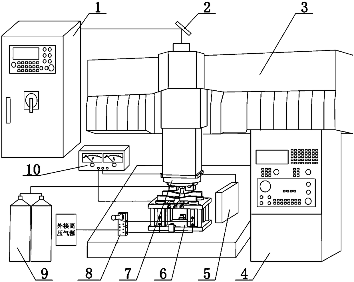
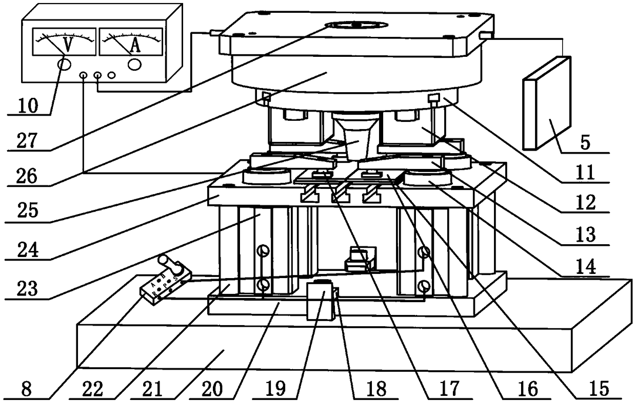
[0081] First, wipe off the oil stains and other dirt on the surface of many pieces of industrial pure nickel Ni201 to be welded with acetone, and then dry them with wind after wiping, and keep them dry and clean. Put industrial pure nickel on the base plate of the electric field, and control the manual switch 8 of the pneumatic valve in the external air circuit connected to the rotary cylinder 23 (the electric-magnetic valve can be used to control the on-off of the air circuit in automatic production), and the rotation can be realized. The transition between the working states of the cylinder 23. Switch the cylinder to working mode, as figure 2 Shown is the clamping working state of the rotary cylinder 23.

[0082] Secondly, set the welding parameters of pure nickel in CNC welding industry: laser power P=1500W, welding speed V=600mm / min, use the mixed gas of helium an...

Example Embodiment

[0085] Implementation Case 2

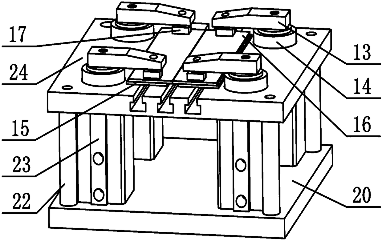
[0086] After the test case 1 is completed, take another piece of processed industrial pure nickel and put it on the electric field generating base plate 24, and toggle the manual switch 8 of the pneumatic valve to make the workpiece pressing block 17 press the workpiece 13. Loosen the screws that fix the NdFeB permanent magnets, shorten the distance between the two permanent magnets, use a magnetic field strength tester to test that the magnetic field strength at the laser focus position is 70mT, and set the parameters of the encoder to control the speed of the direct drive motor. 200r / min. The electric field does not interact with the weld puddle.

[0087] Then start the CO2 laser to weld the industrial pure nickel sheet. After the welding is completed, adjust the manual switch 8 of the pneumatic valve to make the piston of the rotary cylinder 23 rise, and the workpiece pressing block 17 leaves the workpiece surface to take off the workpiece. ...

Example Embodiment

[0088] Implementation Case 3

[0089] After the test case 2 is completed, another piece of processed industrial pure nickel is placed on the electric field generating base plate 24, and the manual switch 8 of the pneumatic valve is toggled to make the workpiece pressing block 17 press the workpiece 13. The magnetic field strength is still 70mT, and the parameters of the encoder are set to control the speed of the direct drive motor to 600r / min. Start the power supply 10 and adjust the output voltage to 20V.

[0090] Then start the CO2 laser to weld the industrial pure nickel sheet. After the welding is completed, adjust the manual switch 8 of the pneumatic valve to make the piston of the rotary cylinder 23 rise, and the workpiece pressing block 17 leaves the workpiece surface to take off the workpiece. Using wire cutting along the direction perpendicular to the welding direction, the metallographic sample is cut in the cross section. The surface of the sample is ground and p...


PUM


Abstract

The invention discloses a rotary electric field and magnetic field synchronously assisted laser welding device and method and belongs to the field of laser welding. The welding device comprises an electricity and magnet regulating device and a positioning and clamping tooling. Supporting columns and rotary air cylinders in the positioning and clamping tooling are mounted on a bottom plate. An electric field generation bottom plate is mounted on the supporting columns. Press blocks are mounted on the rotary air cylinders correspondingly. Neodymium iron boron permanent magnets in the electricityand magnet regulating device are fastened to a magnetic field regulating disc. Insulation sleeves, a welding laser head and the magnetic field regulating disc are mounted on a direct drive motor. Thedirect drive motor is mounted on a main shaft. The two poles of an electric field power source are connected to the electric field generation bottom plate and the welding laser head correspondingly.By means of the device and method provided by the invention, easy, convenient and fast regulation of a rotary magnetic field and a steady electric field can be achieved, continuous regulation of the intensity can be achieved, synchronous movement of the electric field and the magnetic field along with welding laser beams is guaranteed, and therefore, the forming quality of laser welding joints isimproved by setting the reasonable laser technological parameters including the power, the focal length, the defocusing amount, the helium protective gas flow rate and the like.

Description

technical field [0001] The invention belongs to the technical field of laser processing, and relates to a device and method for synchronously assisted laser welding by a rotating electric-magnetic field, specifically a method for synchronously assisting laser welding based on a rotating magnetic field and a constant electric field of a permanent magnet and its welding device. Background technique [0002] Laser welding is a welding method that uses continuous or pulsed laser beams as a heat source to melt and connect workpieces. It has the characteristics of fast welding speed, large aspect ratio, and small deformation. With the rapid development of industrial production and the continuous development of new materials, the performance requirements of welded structures are getting higher and higher. Laser welding has been widely used for its advantages of high energy density, deep penetration, high precision, and strong adaptability. [0003] The electro-magnetic field assist...

Claims


Application Information

Patent Timeline
IPC IPC(8): B23K26/21B23K26/12B23K26/70
CPCB23K26/123B23K26/21B23K26/702
Inventor 石岩闫胜鸿刘佳李云峰
Owner CHANGCHUN UNIV OF SCI & TECH
Why Eureka
Try Eureka