Metal component optimization method based on additive process forming and forming equipment with same

A metal component and additive process technology, applied in the direction of additive processing, etc., can solve the problems of large energy consumption, complicated process route, and long process time, and achieve the effect of improving surface hardness, high surface finish, and friendly working environment

Inactive Publication Date: 2019-01-08
SHENZHEN GRADUATE SCHOOL TSINGHUA UNIV
View PDF12 Cites 11 Cited by
  • Summary
  • Abstract
  • Description
  • Claims
  • Application Information

AI Technical Summary

Problems solved by technology

[0005] In order to overcome the deficiencies of the prior art, the present invention provides an optimization method and molding equipment for metal components based on additive process molding, which are used to solve the need to build a vacuum environment in the prior art, the process route is complex, and the equipment cost is high; a large amount of equipment is consumed energy, which is not conducive to energy saving and environmental protection, the process takes a long time, and the overall efficiency is low, etc.

Method used


Image

  • Metal component optimization method based on additive process forming and forming equipment with same
  • Metal component optimization method based on additive process forming and forming equipment with same
  • Metal component optimization method based on additive process forming and forming equipment with same

Examples


Embodiment 1

[0044] First, the metal component is formed by the additive process, specifically, the metal powder is fused according to the preset 3D printing filling scanning path. The fusion methods of the metal powder used in this embodiment include but are not limited to laser fusion, flame fusion, and plasma. Body fusion, welding fusion and electric heat source fusion, and the metal components formed by fusion have several cladding layers. The metal components in this embodiment are 316L stainless steel components.

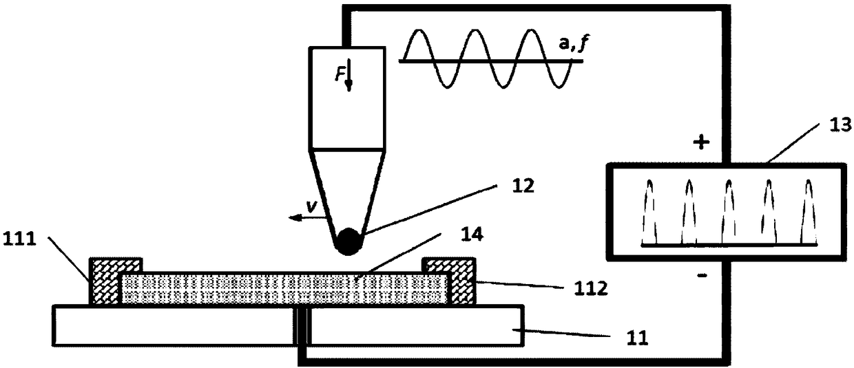
[0045] Then perform the step of ultrasonic rolling treatment and the step of applying pulse current. In this embodiment, the scheme of applying pulse current while performing ultrasonic rolling treatment is adopted. refer to figure 1 , shows a schematic structural diagram of the optimization equipment implementing the optimization method in the present invention. As shown in the figure, the optimization equipment includes a support platform 11, which is used to support a...

Embodiment 2

[0054] First, the metal component is formed by the additive process, specifically, the metal powder is fused according to the preset 3D printing filling scanning path. The fusion methods of the metal powder used in this embodiment include but are not limited to laser fusion, flame fusion, and plasma. Body fusion, welding fusion and electric heat source fusion, and the metal components formed by fusion have several cladding layers. The metal components in this embodiment are 316L stainless steel components.

[0055] Then perform the step of ultrasonic rolling treatment and the step of applying pulse current. In this embodiment, the scheme of performing ultrasonic rolling treatment first and then applying pulse current is adopted. refer to Figure 4 , shows a schematic structural diagram of the optimization equipment implementing the optimization method in the present invention. As shown in the figure, the optimization equipment includes a support platform 21, and an ultrasoni...

Embodiment 3

[0062] The difference between this embodiment and Embodiment 1 and Embodiment 2 is that in the above embodiment, the optimization step of the component is carried out independently of the molding step, and the optimization equipment and the molding equipment are relatively independent equipment; in this embodiment, the optimization Equipment and molding equipment are centralized. refer to Figure 5 , shows a schematic structural view of the molding equipment implementing the optimization method in the present invention. As shown in the figure, the molding equipment includes a support platform 31, an ultrasonic rolling head 32 and a pulse power supply 33. The connection relationship between the support platform 31, the ultrasonic rolling head 32 and the pulse power supply 33 is the same as that of the first embodiment, and will not be repeated here. The molding device also includes a printing head 34 for realizing additive molding, and the printing head 34 can adopt the existi...


PUM

PropertyMeasurementUnit
frequencyaaaaaaaaaa
thicknessaaaaaaaaaa

Abstract

The invention relates to the technical field of metal component additive manufacturing, and discloses a metal component optimization method based on additive process forming and forming equipment withthe same. The metal component optimization method comprises the following steps that a metal component prepared by an additive process is arranged, and a cladding layer is arranged on the metal component; ultrasonic rolling treatment is performed on the cladding layer; and a pulse current is applied to the metal component. According to the method and the equipment, an internal structure of the metal component can be regulated, the defects of holes, microcracks and the like can be reduced, the compactness of a base body can be improved, the stress state of the component is regulated, the surface quality, the precision and the stability of the metal component are improved, the comprehensive service performance of the metal component, such as the surface hardness, the wear resistance, the fatigue resistance and the corrosion resistance, can further be improved, extra heat treatment is not needed, and the metal component optimization method based on the additive process forming and the forming equipment with the same have the advantages of being efficient, stable in the process, safe, reliable, friendly in working environment, energy-saving, environmentally friendly, green and pollution-free and the like.

Description

technical field [0001] The invention relates to the technical field of additive manufacturing of metal components, in particular to an optimization method for improving the performance of metal components formed by an additive process, and forming equipment for implementing the optimization method. Background technique [0002] As a strategic emerging industry, 3D printing (additive manufacturing) technology integrates multiple disciplines such as digital technology, manufacturing technology, laser technology and new material technology, and is known as a representative technology that is expected to become the "third industrial revolution". . Compared with traditional manufacturing processes such as machining and mold forming, additive manufacturing changes three-dimensional solid processing into several two-dimensional plane processing, which greatly reduces the complexity of manufacturing and has great advantages in rapid production and flexibility. At present, the rapid...

Claims


Application Information

Patent Timeline
Patent Type & Authority Applications(China)
IPC IPC(8): B23P9/00B23P9/02B22F3/24B33Y40/00
CPCB22F3/24B23P9/00B23P9/02B33Y40/00
Inventor 唐国翌宋国林李丘林刘伟
Owner SHENZHEN GRADUATE SCHOOL TSINGHUA UNIV
Why Eureka
Try Eureka