Selective catalytic reduction denitration reactor

A denitrification reactor and reactor technology, applied in chemical instruments and methods, gas treatment, dispersed particle separation, etc., can solve the problems of high investment cost and operation cost, affecting the stable operation of the boiler, and large amount of high-temperature flue gas, etc., to achieve Save investment costs, improve economic and social benefits, and lower flue gas temperature

Inactive Publication Date: 2019-01-11
宫子凡
View PDF5 Cites 2 Cited by
  • Summary
  • Abstract
  • Description
  • Claims
  • Application Information

AI Technical Summary

Problems solved by technology

If the heating device mentioned in the above patent uses fuel as the heat source (such as natural gas stove, coal-fired hot blast stove), secondary pollution will be generated, and the amount of high-temperature flue gas required is very large; if electric heating is used to heat the air into high-temperature analytical Gas, also requires very powerful electric heaters
Its investment cost and operating cost are very high, and the stable operation of the boiler will be affected when the catalyst is heated

Method used


Image

  • Selective catalytic reduction denitration reactor
  • Selective catalytic reduction denitration reactor

Examples


Embodiment Construction

[0020] The present invention will be described in further detail below in conjunction with the accompanying drawings and specific embodiments, to help those skilled in the art have a more complete, accurate and in-depth understanding of the inventive concept and technical solutions of the present invention. The protection scope of the present invention includes but is not limited to In the following examples, without departing from the spirit and scope of the present application, any modifications made to the details and forms of the technical solutions of the present invention fall within the protection scope of the present invention.

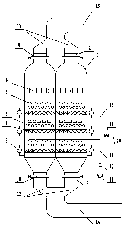
[0021] Accompanying drawing is a kind of specific embodiment of the present invention. This embodiment comprises reactor body 1, and described reactor body 1 comprises several independent reaction chambers, and the top and the bottom of each reaction chamber of described reactor body 1 are all provided with reactor inlet 2 and reactor outlet 3,...


PUM


Abstract

The invention discloses a selective catalytic reduction denitration reactor, comprising a reactor body, wherein the top of the reactor body is connected with a gas inlet pipeline and the bottom of thereactor body is connected with a gas outlet pipeline; the reactor body is internally provided with flow equalization grids, blowing drying devices, optical wave heating devices and catalyst layers; the flow equalization grids are located at the upper part in the reactor body; the reactor body is internally provided with a plurality of catalyst layers; an optical wave heating device is arranged above each catalyst layer; the blowing drying devices are arranged above the optical wave heating devices; an online micro differential pressure detection device is arranged at each of the upper part and lower part of each catalyst layer; the blowing drying device communicate with a high-pressure and high-temperature steam pipeline and a gas outlet bypath respectively through a steam pipeline; and the gas outlet bypath communicates with the gas outlet pipeline. The selective catalytic reduction denitration reactor is high in denitration efficiency and the NOx emission concentration can be controlled within an extremely low emission value and is lower than national ultralow emission standards.

Description

technical field [0001] The invention relates to flue gas purification and denitrification treatment applicable to the waste incineration industry, in particular to a selective catalytic reduction denitrification reactor. Background technique [0002] Conventional disposal methods of municipal solid waste include landfill, incineration and composting. Waste incineration has attracted much attention due to its advantages of complete harmlessness, large capacity reduction, short processing time, heat recovery and small footprint. The core of incineration treatment technology is the reasonable organization of combustion and the prevention and control of secondary pollution. The secondary pollutants caused by waste incineration to the environment mainly come from the flue gas produced during the incineration process. Incineration flue gas contains a large amount of acid gas (HCl, SO 2 , HF, HBr, NO x etc.), organic pollutants (PCDDs, PCDFs, etc.), particulate matter and heavy...

Claims


Application Information

Patent Timeline
IPC IPC(8): B01D53/86B01D53/56
CPCB01D53/8625B01D2258/0283
Inventor 宫子凡
Owner 宫子凡
Why Eureka
Try Eureka