Multi-beam coaxial laser damage threshold test device and realization method

A technology of laser damage threshold and testing device, which is used in measurement devices, optical instrument testing, testing optical performance, etc., can solve the problem of difficulty in ensuring multi-beam collimation and the same beam waist position, increasing equipment and testing costs, and optical component dispersion. and other problems, to achieve the effect of wide measurement object range, high sensitivity and good repeatability

Active Publication Date: 2019-01-11
XIAN TECH UNIV
View PDF9 Cites 17 Cited by
  • Summary
  • Abstract
  • Description
  • Claims
  • Application Information

AI Technical Summary

Problems solved by technology

In order to meet the needs of different users, many units have built their own laser damage threshold test platforms. Some test wavelengths are 1064 nm, and some are 532 nm. However, these units currently only use a single laser to test samples. bundle
If you need to test the laser damage threshold of two wavelengths of 1064 nm and 532nm, you need to use two independent laser damage threshold test systems, or integrate two independent test systems on one platform, the essence is still two sets Optical system, this structure not only increases the cost of equipment and testing, but also is very inefficient, so it is necessary to develop testing equipment that can measure multiple laser damage thresholds
[0005] The reason why it is difficult to use multi-beam coaxial optical system at present is that there is chromatic dispersion in the optical components, and the focal length and image plane position of the optical system are different for different laser beams, which makes it difficult for the coaxial optical system to ensure the collimation of multiple beams and the same beam Waist position, resulting in serious measurement errors

Method used


Image

  • Multi-beam coaxial laser damage threshold test device and realization method

Examples


Embodiment

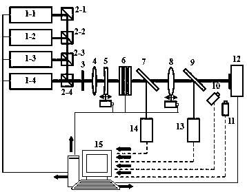
[0032] A multi-optical coaxial laser damage threshold testing device, the output wavelengths are λ 1 , lambda 2 , lambda 3 and lambda 4 The four high-energy pulsed lasers 1-1, laser 2 1-2, laser 3 1-3 and laser 4 1-4, the four laser beams pass through cube prism 1 2-1, cube prism 2 2-2, and cube prism Three 2-3 and four cubic prisms 2-4 reflect (or transmit) and enter the same optical axis system, and pass through the switch baffle plate 3 on the main optical path in turn, and enter the positive lens 4 and negative lens 5 of the variable-pitch beam expander system , an attenuator 6, a first beam splitter 7, a displacement focusing lens 8, a second beam splitter 9, a sample stage 12, a CCD camera 10, a fiber optic spectrometer 11, a beam analyzer 13 and an energy meter 14.

[0033] The output wavelengths of the four high-energy pulsed lasers are 1064 nm, 532 nm, 355 nm and 266 nm respectively, the pulse width is 10 ns, the output laser beam spot is a Gaussian spot with a dia...


PUM


Abstract

The invention discloses a multi-beam coaxial laser damage threshold test device and a realization method. According to the multi-beam coaxial laser damage threshold test device, four high-energy pulsed lasers are adopted, reflected by corresponding prisms and then enter a coaxial optical system, four light beams use one set of system and a computer control processing system, a variable-interval positive lens and a variable-interval negative lens are utilized to constitute a beam expanding system, the optical interval of the beam expanding system is adjusted, and thus collimated beam expandingof laser beams with different wavelengths can be achieved; and a stepper motor is adopted to precisely control the position of a focusing lens, and focal lengths of the different laser wavelengths arecompensated, so that it is ensured that laser is transmitted to the test surface, and the size and defocusing amount of a light spot are constant. According to the multi-beam coaxial laser damage threshold test device, integration, automation and intellectualization of a test system are achieved, thin film damage can be judged quickly and accurately in real time online, and laser damage thresholds of the various different wavelengths can be measured through the same test device.

Description

technical field [0001] The invention relates to a multi-optical coaxial laser damage threshold testing device and a realization method. Background technique [0002] In high-power and high-energy laser systems, there are a large number of optical components, and the surfaces of these components often need to be coated with thin films to achieve specific optical properties. Studies have shown that the damage of optical components under strong laser is completely determined by the anti-laser ability of the surface film of the component. Therefore, the laser damage threshold has become an indispensable performance index of optical components and thin film devices. Efficient measurement of thin film laser damage threshold has become an important technical problem to be solved urgently. [0003] Therefore, for many years, the research on the damage process and threshold testing method of laser and optical dielectric thin films has always been a research hotspot at home and abro...

Claims


Application Information

Patent Timeline
Patent Type & Authority Applications(China)
IPC IPC(8): G01M11/02
CPCG01M11/0257
Inventor 徐均琪苏俊宏杨利红梁海锋李建超时凯吴慎将诗云云
Owner XIAN TECH UNIV
Why Eureka
Try Eureka