Laser differential confocal tomography focusing method and device

A differential confocal and laser technology, which is used in the measurement of aspheric components, optical components, optical imaging and detection, and optical systems, can solve the problem of poor anti-scattering ability of the surface, limited ability of confocal microscope axial resolution, measurement Long time and other problems, to achieve the effect of simplifying the system structure and assembly process, improving the accuracy of optical focusing, and high-precision tomographic focusing

Active Publication Date: 2019-01-22
BEIJING INSTITUTE OF TECHNOLOGYGY
View PDF5 Cites 37 Cited by
  • Summary
  • Abstract
  • Description
  • Claims
  • Application Information

AI Technical Summary

Problems solved by technology

[0002] There is a common problem in the field of optical measurement: due to the limitation of the diffraction limit, the further improvement of the focusing ability of optical measurement is restricted, which in turn restricts the improvement of the accuracy performance of detection instruments
Interferometric fixed focus is mainly used for fixed focus aiming on the surface of components, which restricts its application in the measurement of internal interface parameters such as lens refractive index, thickness and spacing;
[0005] 2) Poor anti-surface scattering ability
Surface scattering will destroy the conditions for forming interference, which will make it difficult for interferometric focusing to adapt to measurement fields such as non-perfect polished surface optical components, metal surfaces, and ceramic surfaces, hindering the scope of application of the interferometric focusing measurement method;
[0006] 3) Interference fixed focus speed is slow
The interference focusing method based on the acquisition and analysis of full-frame interference fixed-focus images will inevitably reduce the speed and accuracy of optical focusing, and it is difficult to achieve fast fixed-focus measurement, resulting in long measurement time and large system drift, which will ultimately affect measurement accuracy;
[0007] 4) Poor ability to resist environmental interference
However, due to the limitation of the diffraction limit and other factors, the ability to improve the axial resolution of the confocal microscope is limited only by increasing the numerical aperture NA of the objective lens and reducing the wavelength λ of the light wave.
[0011] In order to avoid the influence of diffraction focal depth on axial resolution and focus accuracy, the inventor applied for a Chinese patent "Differential Confocal Scanning Detection Method with High Spatial Resolution" (Patent No.: ZL200410006359.6), which significantly improved The axial resolution ability, axial fixed focus ability and environmental anti-disturbance ability of the confocal microscope system are improved. However, because the patented technology uses two detection optical paths for differential subtraction detection, it has high requirements for assembly accuracy and complex systems. At the same time, the high-resolution differential confocal microscopy technology is mainly aimed at the field of microscopic imaging technology

Method used


Image

  • Laser differential confocal tomography focusing method and device
  • Laser differential confocal tomography focusing method and device
  • Laser differential confocal tomography focusing method and device

Examples


Embodiment 1

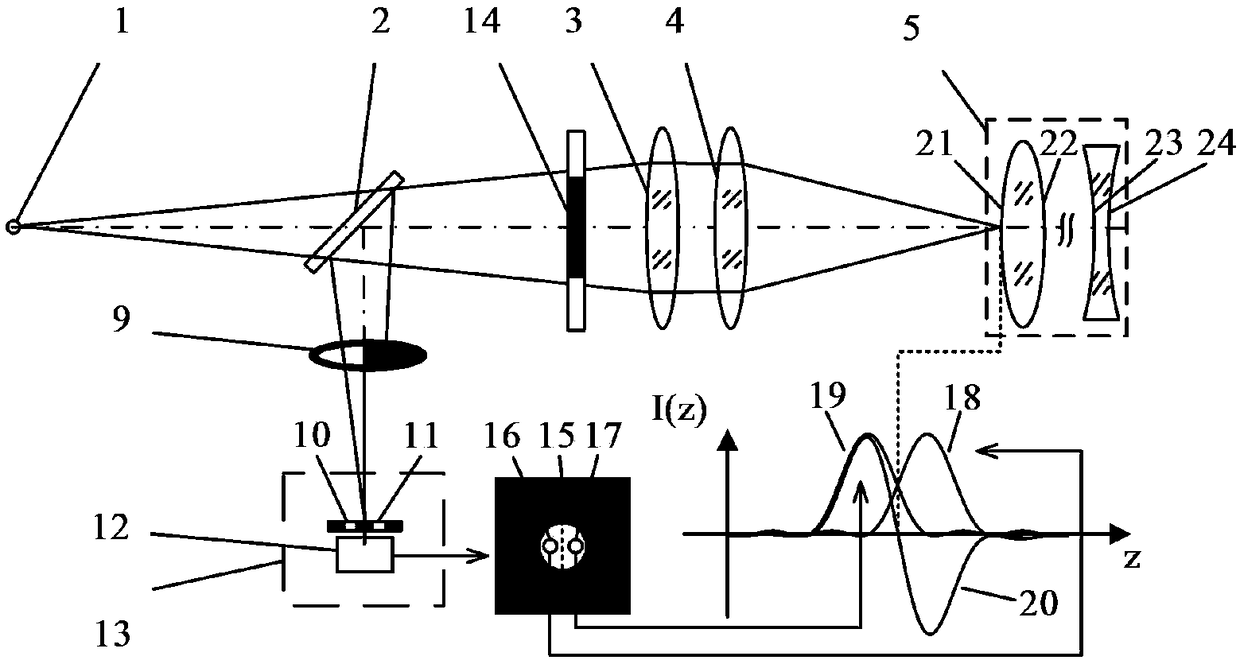
[0054] as attached Figure 5 As shown, a laser differential confocal tomographic fixed focus device includes a laser 31, an optical fiber 32, and a point light source 1, and a beam splitter 2, a collimator lens 3, and an objective lens 4 placed in the light emitting direction of the point light source 1 in sequence, It also includes a D-shaped rear pupil 9 placed in the reflection direction of the beam splitter 2 and a split-pupil differential confocal detection system 13 composed of a microscopic objective lens 27 and a CCD 28; the main control computer 33 is connected with a motor drive system 34, It drives the linear guide rail 35 to drive the measured sample 5 to scan along the optical axis.

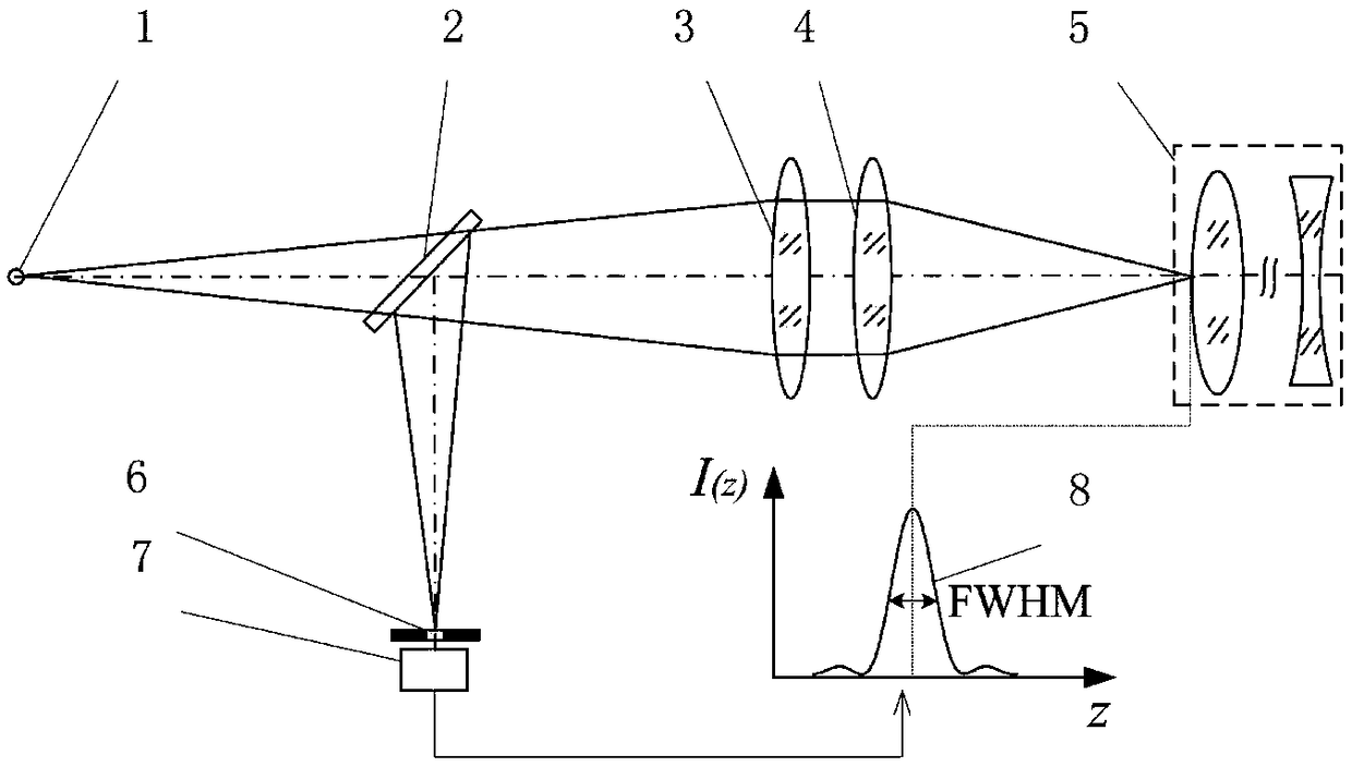
[0055] Usually the split-pupil differential confocal detection system 13 has two forms, one is the attached figure 2 The split-pupil differential confocal detection system using pinhole detection is shown, and the other is the attached Figure 5 A split-pupil differential confocal...

Embodiment 2

[0069] Such as Image 6 As shown, a laser differential confocal tomographic fixed focus device, its measurement steps are the same as in Embodiment 1, the difference is that a circular rear pupil 37 is used to block the measurement beam, and then realize the laser differential confocal Tomographic focus.


PUM


Abstract

The present invention relates to a laser differential confocal tomography focusing method and device, and relates to the technical field of optical imaging and detection. The method uses a rear pupilto block half of a measurement beam, uses a spectroscopic differential confocal detection system to detect the unblocked measurement beam, and uses an absolute zero point of a differential confocal response curve to achieve high precision tomographic focusing. The method organically combines a laser differential confocal technique and a ray tracing technique to establish a ray tracing and compensation model to eliminate influence among each fixed focal surface parameters, and achieves fast trigger of focus through data near a linearly fitting absolute zero point. The method can obtain the differential confocal response curve by using only one detector, and realizes the tomographic focusing through the absolute zero point of the differential confocal response curve, greatly simplifies system structure, in the same time, avoids error introduced by adjustment inaccuracy, and greatly improves precision of focusing. The method will provide a new technical approach to the field of confocal imaging/detection.

Description

technical field [0001] The invention belongs to the technical field of optical imaging and detection, and can be used in the technical fields of optical elements, optical systems, and aspheric element measurement. Background technique [0002] There is a common problem in the field of optical measurement: due to the limitation of the diffraction limit, the further improvement of the focusing ability of optical measurement is restricted, which in turn restricts the improvement of the accuracy performance of detection instruments. For example, in the measurement of spherical optical element parameters, in addition to the surface shape parameters, the high-precision measurement of its radius of curvature, lens thickness, refractive index, focal length, and lens group spacing mainly depends on the focus accuracy of the interface between optical measurement elements, especially Tomographic focusing accuracy between optical component interfaces. In fact, how to improve the focusi...

Claims


Application Information

Patent Timeline
Patent Type & Authority Applications(China)
IPC IPC(8): G01N21/63G01N21/01
CPCG01N21/01G01N21/63
Inventor 赵维谦邱丽荣杨帅王允
Owner BEIJING INSTITUTE OF TECHNOLOGYGY
Why Eureka
Try Eureka