Single-layer ferromagnetic materials with current-driven magnetic moment flipping and their applications

A ferromagnetic material, current-driven technology, applied in the direction of material selection, magnetic field-controlled resistors, static memory, etc., can solve the problems of unfavorable device thermal stability, increase the complexity of device manufacturing process, etc., and achieve simplified architecture and manufacturing The effect of process, high thermal stability, great cost advantage

Active Publication Date: 2019-01-25
TONGJI UNIV
View PDF3 Cites 7 Cited by
  • Summary
  • Abstract
  • Description
  • Claims
  • Application Information

AI Technical Summary

Problems solved by technology

However, the spin-orbit moments generated in current bilayers strongly depend on the properties of the nonmagnetic metal layer / ferromagnetic layer interface, thus requiring the ferromagnetic layer to be very thin (<2 nm), which is not conducive to Device Thermal Stability
On the other hand, the use of double-layer films will also increase the complexity of the device fabrication process

Method used


Image

  • Single-layer ferromagnetic materials with current-driven magnetic moment flipping and their applications
  • Single-layer ferromagnetic materials with current-driven magnetic moment flipping and their applications
  • Single-layer ferromagnetic materials with current-driven magnetic moment flipping and their applications

Examples


Embodiment 1

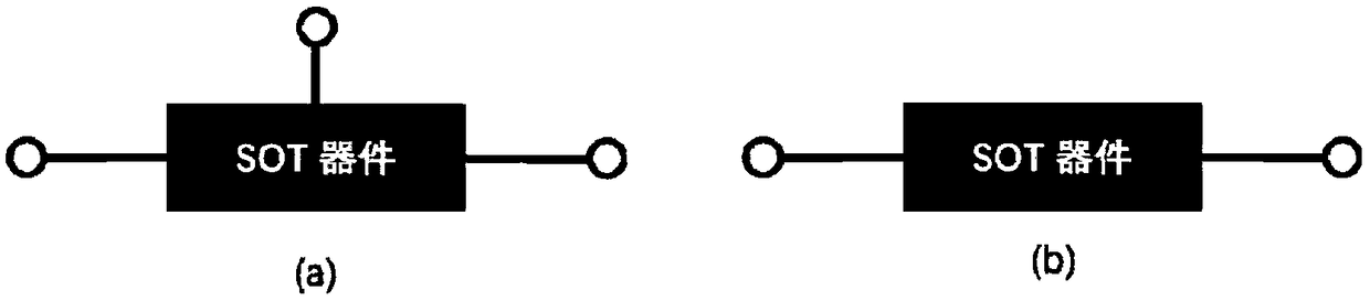
[0030] like Figure 4 As shown, an embodiment of using the present invention to manipulate the magnetic moment of a single-layer ferromagnetic layer and detect the state of the magnetic moment, the single-layer ferromagnetic layer is prepared into the shape of a Hall bar as shown in the figure by using micro-nano processing technology. 201, 202 serve as two electrodes for applying current, and 203, 204 serve as two electrodes for measuring voltage. Since ferromagnetic materials have anomalous Hall effect, and the anomalous Hall resistance R H is proportional to the magnetic moment m in the normal direction of the film, that is, R H ∝m, so by measuring the abnormal Hall resistance value between electrodes 203 and 204, the direction of the magnetic moment of the ferromagnetic layer can be known. First, apply an auxiliary magnetic field along the direction from 201 to 202, and then apply a writing current I between the electrodes 201 and 202 W , the current can be positive or ...

Embodiment 2

[0034] In this embodiment, the present invention is used to construct the storage unit of the MRAM, that is, the magnetic tunnel junction. Image 6 A schematic diagram of the structure of this magnetic tunnel junction is given, from bottom to top there are 301 magnetic storage layer, 302 intermediate layer, 303 magnetic reference layer. 301 is a functional layer implementing the technology of the present invention, so the magnetic layer 301 should have a strong spin-orbit coupling effect. 302 The middle layer is oxide or non-magnetic metal. The 303 magnetic reference layer can use the same ferromagnetic material as that of the 301 layer, or can use a different ferromagnetic material. Image 6 A schematic diagram of the operation of writing data using the technology of the present invention is also given, that is, a write current is applied in the 301 layer, and the magnetic moment of the 301 layer is reversed to a specific direction by using the spin torque effect of the curr...


PUM


Abstract

The invention relates to a single-layer ferromagnetic material with magnetic moment flipping driven by current and application thereof. The single-layer ferromagnetic material is a thin film with thickness of 1-100nm, has strong spin-orbit coupling action, generates spin moment after current is introduced, and flips self-magnetic moment of the single-layer ferromagnetic material by spin moment. The invention utilizes current to generate spin moment in monolayer ferromagnetism, and inverting the magnetic moment of the single-layer ferromagnetism by using the spin moment, The device can be applied to magnetic random access memory and spin logic device, and the device based on the technology of the invention can have unlimited thickness so as to have higher thermal stability, that is, nonvolatility, and simplify the structure and preparation process of the device in application, and has great cost advantage.

Description

technical field [0001] The invention relates to a single-layer ferromagnetic material, in particular to a technique for driving the magnetic moment reversal of a single-layer ferromagnetic material by electric current and its application. Background technique [0002] The magnetic random access memory uses the magnetic moment direction of the magnetic material as the information carrier, and has the advantages of non-volatility, fast read and write speed, and high storage density. Spin logic devices are based on the emerging spintronics, which use spin to perform logic operations, and have the advantage of ultra-low power consumption. Both MRAM and spin logic devices need to use current to manipulate the magnetic moment or magnetization state of magnetic materials. At present, there are two mainstream technologies that can achieve this manipulation, namely spin transfer torque (Spin transfer torque, STT) technology and spin Orbit torque (spin orbit torque, SOT) technology. ...

Claims


Application Information

Patent Timeline
Patent Type & Authority Applications(China)
IPC IPC(8): H01L43/08H01L43/10G11C11/16
CPCG11C11/161H10N50/85H10N50/10
Inventor 丘学鹏唐猛周仕明
Owner TONGJI UNIV
Why Eureka
Try Eureka