Ultra-high power limiter mmic and its preparation method based on bonding transfer

A super-power, limiter technology, applied in the field of super-power limiter MMIC and preparation based on bonding transfer, to achieve the effect of avoiding integration, excellent performance and high integration

Active Publication Date: 2021-01-26
NO 55 INST CHINA ELECTRONIC SCI & TECHNOLOGYGROUP CO LTD
View PDF5 Cites 0 Cited by
  • Summary
  • Abstract
  • Description
  • Claims
  • Application Information

AI Technical Summary

Problems solved by technology

[0004] The purpose of the present invention is to provide a super-power limiter MMIC based on bonding transfer and its preparation method, to solve the problems of the preparation of high-power PIN tubes and the integration of discrete PIN tubes and circuits

Method used


Image

  • Ultra-high power limiter mmic and its preparation method based on bonding transfer
  • Ultra-high power limiter mmic and its preparation method based on bonding transfer
  • Ultra-high power limiter mmic and its preparation method based on bonding transfer

Examples


preparation example Construction

[0041] A method for preparing an ultra-high power limiter MMIC based on bonding transfer, comprising the following steps:

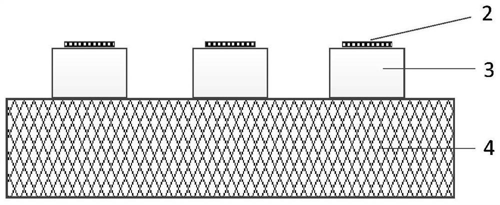
[0042] ① Prepare PIN mesa structure and upper electrode 2 on the front side of Si wafer 4: prepare PIN mesa structure on Si wafer 4, the mesa structure is Si PIN die 3, and the height of PIN mesa is from 1um-50um according to design requirements, And wash it with diluted hydrochloric acid HCl, acetone, alcohol and deionized water, put it into a dryer for drying, such as figure 2 shown.

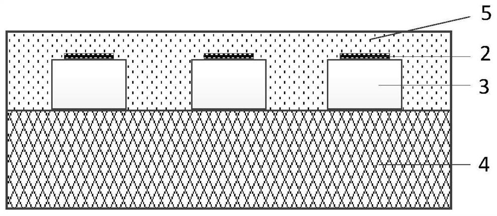
[0043] ② Spin-coating the adhesive 5 on the front side of the Si wafer 4: drop-coating the adhesive 5 on the front side of the Si wafer including the PIN mesa structure, the adhesive 5 selected is wax, BCB or photoresist. Set the spin coating speed to 1000-5000 rpm according to the required thickness, and the spin coating time is 30 seconds to 1 minute. Put the Si PIN tube wafer coated with adhesive 5 face up on the hot plate for pre-baking Bake with the hot plate temp...

Embodiment

[0055] A method for preparing an ultra-high power limiter MMIC based on bonding transfer, comprising the following steps:

[0056] ① Prepare the PIN mesa structure on the Si wafer, the PIN mesa height is 5um, prepare the PIN upper electrode, clean it with diluted hydrochloric acid HCl, acetone, alcohol and deionized water, and put it in a dryer for drying;

[0057] ②Drop-coat an appropriate amount of high-temperature wax on the front of the Si wafer with the PIN structure, set the spin-coating speed to 2000 rpm, the acceleration to 2000 rpm, and the spin-coating time to 50s; place the Si PIN coated with high-temperature wax Put the tube disc face up on the hot plate for pre-baking, the temperature of the hot plate is set at 110 ° C, and the time is 2 minutes;

[0058] ③Paste the front side of the Si wafer containing the PIN structure and the temporary carrier together, and perform temporary bonding with a bonding machine. The bonding temperature is set at 200°C, the bonding ti...


PUM


Abstract

The invention discloses a super-power limiter MMIC based on bonding transfer and a preparation method thereof. The preparation method comprises: etching a PIN mesa structure and an upper electrode on the front side of a Si wafer; spin coating and adhering the front side of the Si wafer Bond the Si wafer with the front side of the temporary carrier; thin the Si wafer substrate; prepare the lower electrode on the back of the Si wafer; clean the thin layer of the PIN structure supported by the temporary substrate and the completed The SiC substrate prepared by the peripheral circuit; the thin layer of the PIN tube supported by the temporary substrate and the front side of the SiC substrate prepared by the peripheral circuit are bonded and interconnected; the temporary substrate is removed; the etching isolating the PIN mesa; the PIN The structure is interconnected with SiC circuits to obtain an ultra-high power limiter MMIC based on bonding transfer. The invention integrates the high-performance Si PIN limiter into the MMIC to realize the high-integration and high-power limiter MMIC.

Description

technical field [0001] The invention relates to MMIC preparation technology, in particular to a bonding transfer-based ultra-high power limiter MMIC and a preparation method. Background technique [0002] With the application of new-generation high-power amplifiers such as GaN in radar transmitting systems, high-sensitivity devices such as low-noise amplifiers at the front end of the radar receiving system face the risk of being burned by the transmitted leakage power. Therefore, it is necessary to add a larger Power-tolerant, higher-isolation microwave limiter (PIN). When a high-power signal is input, the PIN limiter will greatly attenuate it; and when a low-power signal is input, there is only a small insertion loss. [0003] The traditional Si-based PIN limiter is mainly a discrete PIN diode. Due to the leakage characteristics of the Si substrate, the SiPIN diode cannot be integrated into the circuit, resulting in a large device size. In addition, the thermal conductivi...

Claims


Application Information

Patent Timeline
Patent Type & Authority Patents(China)
IPC IPC(8): H01L27/02H01L21/77
CPCH01L21/77H01L27/02H01L27/0207
Inventor 戴家赟彭龙新吴立枢郭怀新陈堂胜
Owner NO 55 INST CHINA ELECTRONIC SCI & TECHNOLOGYGROUP CO LTD
Why Eureka
Try Eureka