
Integrated coal gasification fuel cell system with CO2 capture

A fuel cell system and integrated coal gasification technology, which can be used in fuel cells, fuel cell additives, fuel cell heat exchange, etc. To achieve the effect of recycling

Pending Publication Date: 2019-02-01
HUANENG CLEAN ENERGY RES INST
View PDF4 Cites 13 Cited by
  • Summary
  • Abstract
  • Description
  • Claims
  • Application Information

AI Technical Summary

Problems solved by technology

[0005] The object of the present invention is to provide an integrated coal gasification fuel cell power generation system with CO2 capture, which solves the problem of existing CO 2 Capture high energy consumption and low efficiency

Method used


Image

  • Integrated coal gasification fuel cell system with CO2 capture

Examples


Embodiment example 1

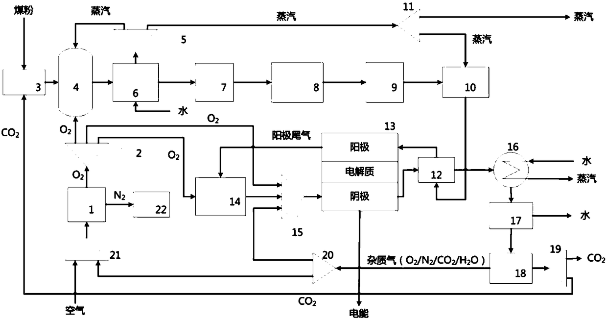
[0045] coal, steam, oxygen and CO 2 Pass it into the gasifier 4 to produce syngas, the temperature of which is 1200°C, and the composition is CO ≈ 67%, H 2 ≈25%, CO 2 ≈7%, the rest is N 2 、H 2 S, COS, CH 4 and other impurities. The synthesis gas first passes through the waste heat recovery device 6 for heat exchange, the temperature is lowered to below 200°C, and then passes into the dust removal device 7, so that the particulate matter content is lower than 10mg / Nm 3 ; then pass into the water vapor shift device 8, the concentration of CO in the gas is reduced to below 10%; then pass into the desulfurization device 9, so that the H 2 The concentrations of S and COS are lower than 1ppm; they are passed into the fuel humidifier 10, and part of the steam generated by the waste heat recovery device 6 is also passed into the fuel humidifier, so that the content of H2O in the syngas is greater than 10%. The syngas is heated to above 500°C through the heat exchanger 12, and th...

Embodiment example 2

[0047] coal, steam, oxygen and CO 2 Pass it into the gasifier 4 to produce syngas, the temperature of which is 1200°C, and the composition is CO ≈ 67%, H 2 ≈25%, CO 2 ≈7%, the rest is N 2 、H 2 S, COS, CH 4 and other impurities. The synthesis gas first passes through the waste heat recovery device 6 for heat exchange, the temperature is lowered to below 200°C, and then passes into the dust removal device 7, so that the particulate matter content is lower than 10mg / Nm 3 ; then pass into the water vapor shift device 8, the concentration of CO in the gas is reduced to below 10%; then pass into the desulfurization device 9, so that the H 2 The concentrations of S and COS are lower than 1ppm; they are passed into the fuel humidifier 10, and part of the steam generated by the waste heat recovery device 6 is also passed into the fuel humidifier, so that the content of H2O in the syngas is greater than 10%. The synthesis gas is heated to above 600°C through the heat exchanger 12,...


PUM


Abstract

The invention provides an integrated coal gasification fuel cell system with CO2 capture. A gasification furnace is used for producing synthetic gas from coal powder, O2, CO2 and steam; then the synthetic gas is subjected to dust removal and purification by using a dust removal device, a water-vapor conversion apparatus and a desulfurizing device, thus preparing synthetic gas containing H2, CO andCH4; then a fuel humidifier is used for the increasing water content of the synthetic gas; a first heat exchanger is used for increasing the temperature of the synthetic gas; then the synthetic gas is fed into the anode of a high temperature fuel cell as a fuel; meanwhile, O2 from an air separation unit and a pure oxygen combustor is fed into the cathode of the high temperature fuel cell, so thatan electrochemical reaction is carried out to the fuel and oxidant, direct current being generated and outputted. In the system, the O2 is used as the oxidant for the cathode of the fuel cell, so that the performance of the fuel cell stack is improved, energy consumption of CO2 capture after the combustion is reduced, and power generation efficiency reaches more than 50%. The system can achieve clean, high-effective and low-carbon utilization of coal resource.

Description

technical field [0001] The invention belongs to the technical field of power generation, in particular to a 2 Captured integral coal gasification fuel cell system. Background technique [0002] Coal is the most important primary energy source in my country, and its basic position in China's energy structure will not change for quite a long time. In recent years, as my country's energy situation has become increasingly severe and the pressure on environmental protection has continued to increase, the demand for reducing carbon dioxide emissions and using coal resources in a clean and efficient manner has become more and more urgent. Technological innovation in the clean and efficient use of coal is one of my country's "Energy Technology Revolution Innovation Action Plans ( 2016-2030)" important content. Coal-to-synthesis gas is a low-cost way of clean and efficient utilization of coal. Syngas can further generate electricity efficiently through fuel cells, which can realize ...

Claims


Application Information

Patent Timeline
IPC IPC(8): H01M8/04007H01M8/04089H01M8/04119H01M8/0662
CPCH01M8/04007H01M8/04089H01M8/04126H01M8/0662Y02E60/50
Inventor 王洪建许世森程健张瑞云任永强
Owner HUANENG CLEAN ENERGY RES INST
Learn More