Electric converter circuit topological structure and control method thereof

A circuit topology, power converter technology, applied in the direction of high-efficiency power electronic conversion, adjustment of electrical variables, control/regulation systems, etc. Oxygen permeability changes and other issues, to achieve the effect of reducing reactive power loss, reducing design and manufacturing difficulty and cost, and fewer power devices

Pending Publication Date: 2019-02-01
ARMY ENG UNIV OF PLA
View PDF4 Cites 31 Cited by
  • Summary
  • Abstract
  • Description
  • Claims
  • Application Information

AI Technical Summary

Problems solved by technology

At present, the resonant frequency of the existing resonance compensation network is determined by the inductance or capacitance, coil self-inductance or mutual inductance in the compensation network. When the relative position between the coils changes, the coil self-inductance, mutual inductance and coupling coefficient between the coils will change accordingly. In addition, under different working temperature environments, the magnetic permeability of the ferrite in the coil structure will also change, which will lead to changes in the electrical parameters of the coil
In addition, the inductance error and capacitance error caused by mass production cannot be avoided
Therefore, in actual work, the resonant frequency will change to a certain extent. If the switching frequency deviates too much from the resonant frequency, it will cause serious problems such as hard switching of the high-frequency inverter, excessive reactive power loss, and reduced power output capability. ; If the switching frequency changes with the resonant frequency, the system will occupy a large frequency bandwidth resource under different working conditions. On the one hand, the relevant domestic and international standards limit the operating frequency range. The frequency range will make the system electromagnetic compatibility design more complicated and increase the system cost

Method used


Image

  • Electric converter circuit topological structure and control method thereof
  • Electric converter circuit topological structure and control method thereof
  • Electric converter circuit topological structure and control method thereof

Examples


Embodiment 1

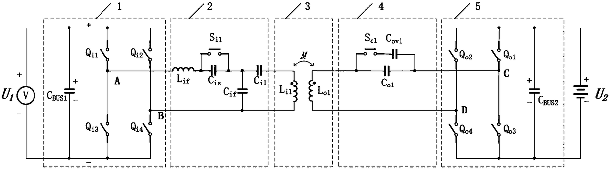
[0082] A power converter circuit topology, characterized in that it includes an input DC power supply U 1 , full bridge inverter circuit 1, primary side resonance dynamic compensation network 2, primary side coil 3L i1 , secondary coil 3L o1 , secondary resonance dynamic compensation network 4, full-bridge synchronous rectification circuit 5 and load battery U 2 ;

[0083] The input DC power U 1 , the full-bridge inverter circuit 1, and the primary-side resonant dynamic compensation network 2 are connected sequentially, and the output terminals of the primary-side resonant dynamic compensation network 2 are respectively connected to the primary-side coil 3L i1 connected at both ends, the secondary coil 3L o1 The two ends of the coil are respectively connected to the input end of the secondary resonance dynamic compensation network 4, and the primary coil 3L i1 , secondary coil 3L o1 The end of the same name is opposite, the output end of the secondary side resonant dynam...


PUM


Abstract

The present invention discloses an electric converter circuit topological structure and a control method thereof. The circuit topology comprises a full-bridge inverter, a primary side resonance dynamic compensation network, a primary side coil, a secondary coil, a secondary resonance dynamic compensation network, a full-bridge synchronous rectifier and a load. The primary side resonance dynamic compensation network employs a structure of connection in series of a compensation inductor and an adjustable resonance capacitor, the secondary resonance dynamic compensation network employs a structure of connection in series of a coil and the adjustable resonance capacitor, in the conditions that system parameters are changed caused by factors such as different coil coupling coefficients, different loads, the temperatures and device production manufacturing errors, the PWM duty ratio of a capacitive switching switch is regulated to generate continuously changed and adjustable equivalent resonant capacitance to perform dynamic compensation for the resonance network to achieve the soft switch of the full-bridge inverter and minimize the reactive power in the energy transmission of the system so as to maximum the electric energy transmission efficiency of the system and effectively enhance the regulation ability of the system output features in a condition of the constant working frequency of the system.

Description

technical field [0001] The invention relates to a power electronic topological circuit, in particular to a power converter circuit topological structure and a control method thereof. Background technique [0002] The near-field power transmission is to convert the high-frequency circuit into an alternating electromagnetic field through the primary coil, and the high-frequency induced current generated in the secondary coil is converted into a DC output by a rectifier circuit. In recent years, this technology has been widely used in wireless charging products for smartphones. In addition, this technology also has broad application prospects in the fields of household robots, industrial robots, and electric vehicles. [0003] In order to improve the energy transmission distance and efficiency, a resonance compensation network can be added to the primary coil and the secondary coil respectively to form a magnetic resonance. At present, the resonant frequency of the existing re...

Claims


Application Information

Patent Timeline
Patent Type & Authority Applications(China)
IPC IPC(8): H02M3/335
CPCH02M3/33523H02M3/33592Y02B70/10
Inventor 李建科
Owner ARMY ENG UNIV OF PLA
Why Eureka
Try Eureka