Material conveying channel, material supplying device and crystal growing system

A supply device and channel technology, applied in the direction of crystal growth, single crystal growth, single crystal growth, etc., can solve the problem of difficulty in effectively controlling the amount and speed of polysilicon material feeding, the difficulty in accurately controlling the positioning of the outlet of the feeding pipe, and the overall height of the feeding mechanism. problems, to achieve the effects of shortening the waiting time, shortening the proportion of feeding time, and improving stability and safety

Pending Publication Date: 2019-02-05
LONGI GREEN ENERGY TECH CO LTD
View PDF7 Cites 5 Cited by
  • Summary
  • Abstract
  • Description
  • Claims
  • Application Information

AI Technical Summary

Problems solved by technology

The patent application with the application publication number CN1153230A provides a solid material feeding system for a furnace. The feeding pipe of the feeding system can selectively change the radial position of the feeding pipe outlet relative to the top of the crucible to avoid splashing and improve The utilization rate of heat energy is high, but the structure of the feeding system is complex, the risk of material clogging exists in the complicated operating mechanism, and the positioning of the outlet of the feeding pipe is difficult to accurately control
The patent with the authorized announcement number CN102312285B provides an external continuous feeding mechanism for single crystal furnaces, which has an inner tube for discharging and an outer tube for discharging, and the polysilicon material is transported from the inner tube for discharging to the outer tube for discharging, which limits The inner diameter of the feeding inner tube is not suitable for bulk materials with large particle sizes; in addition, the overall height of the feeding mechanism is high, which is not conducive to feeding operations and increases operational safety hazards
The patent application with the application publication number CN106400105A discloses that the technical defect of the external feeding device is similar to that of the patent CN102312285B, and it is difficult to effectively control the feeding amount and feeding speed of the polysilicon material

Method used


Image

  • Material conveying channel, material supplying device and crystal growing system
  • Material conveying channel, material supplying device and crystal growing system
  • Material conveying channel, material supplying device and crystal growing system

Examples


Embodiment 1

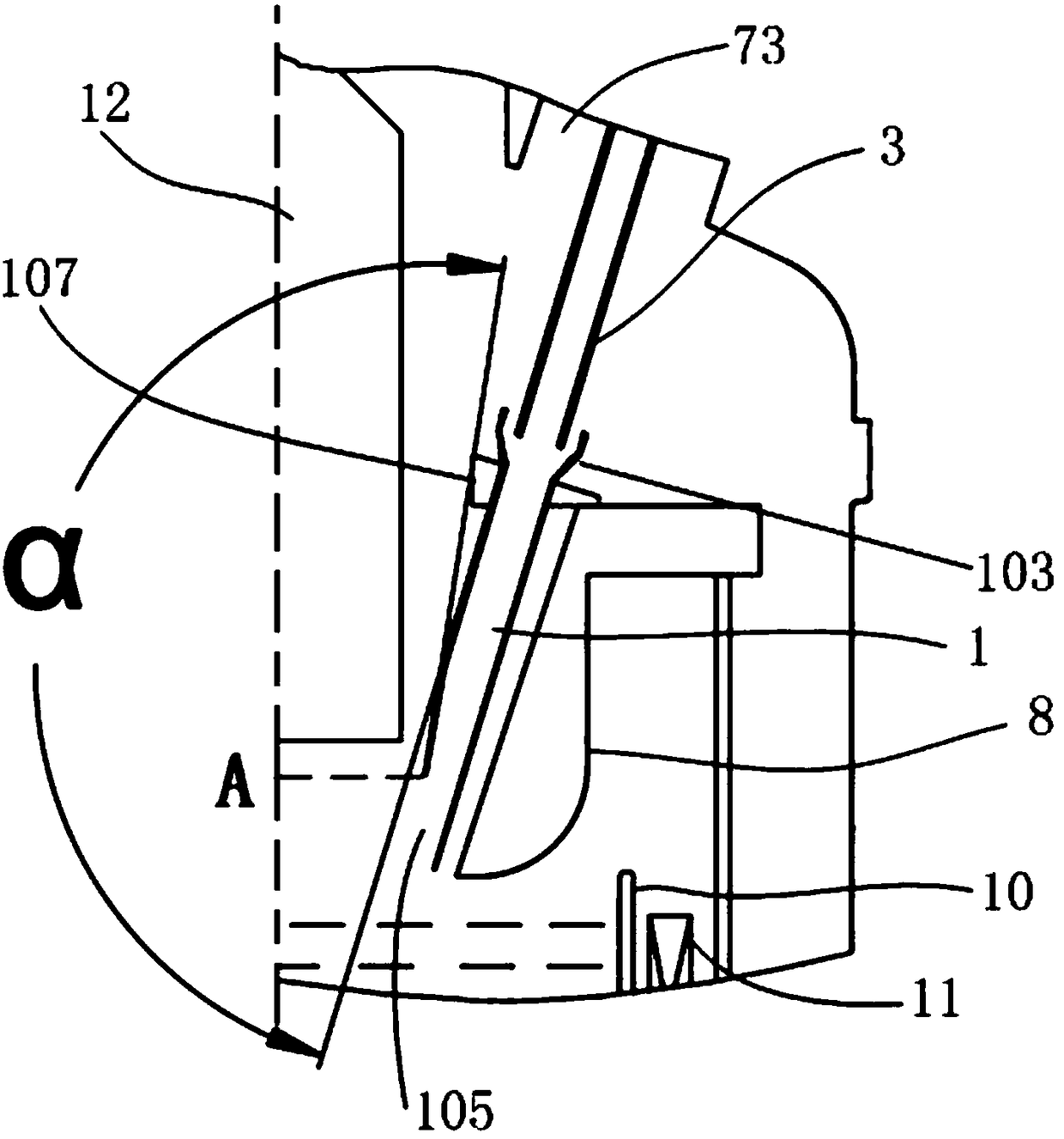
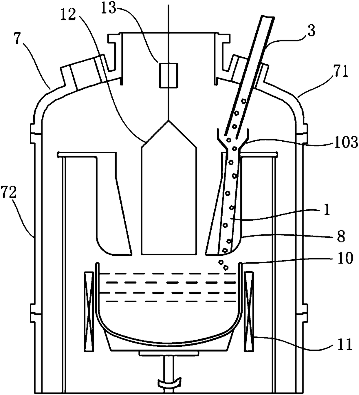
[0093] Figure 6 A material supply device is provided. The material storage mechanism 5 of this material supply device is a material cylinder 51 , and the material delivery mechanism 4 includes a material delivery part 41 and a docking part 44 . At least the storage mechanism 5 is installed on the mobile platform 6 ; The upstream end of the feeding part 41 of the material conveying mechanism 4 is connected to the discharge port of the barrel 51 , and the downstream end of the feeding part 41 is sealingly connected to the docking part 44 . Both the docking portion 44 and the downstream feeding mechanism 2 are arranged outside the furnace cover 71 . The feeding mechanism 2 docks with the opening 73, and the feeding passage 3 is set inside the feeding mechanism 2. The feeding passage 3 is connected to the feeding lifting device 23 of the feeding mechanism 2. Under the action of the feeding lifting device 23, the feeding passage 3 through the opening 73 to realize its expansion...

Embodiment 2

[0110] This section gives the second preferred embodiment of the material supply device, see Figure 7 . The material storage mechanism 5 of this material supply device is still a material barrel 51. For the description of the material storage mechanism 5, refer to Embodiment 1 for details, and will not be repeated here. Different from Example 1, Figure 7 A material guide bellows 53 is arranged at the material outlet of the shown material storage mechanism 5 . The upstream end of the material guide bellows 53 is connected to the material outlet of the storage mechanism 5 through a flange seal, and the downstream end of the material guide bellows 53 is connected to the material delivery mechanism 4 through a flange seal. The material in the barrel 51 naturally falls into the barrel 51 through the material guide bellows 53 under the action of gravity. The setting of the material guide bellows 53 can buffer the extrusion of the material barrel 51 full of materials to the mate...

Embodiment 3

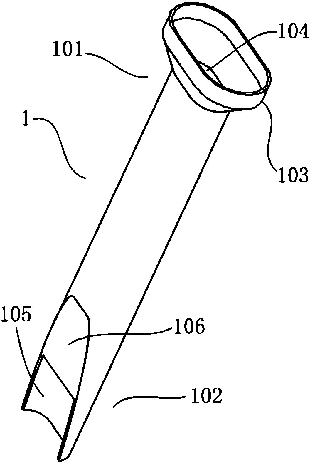
[0118] This section gives the third preferred embodiment of the material supply device, see Figure 8 , Figure 11 and Figure 12 . Refer to Embodiment 2 for the arrangement of the storage mechanism 5 and the feeding mechanism 2 of this material supply device, as well as the isolation valve 9 on the furnace body 7 . It should be added that, if Figure 11 As shown, as a preferred embodiment, at least part of the space between the feeding channel fixing sleeve 21 and the feeding channel 3 is filled with a buffer layer 24, and the buffer layer 24 can be filled with flexible materials to better protect the feeding Pathway 3.

[0119] The material conveying mechanism 4 in this part can be realized by means of screw propulsion feeding, but its specific structure can be appropriately adjusted according to the intention of the present invention, for example, a combined structure combining screw propulsion feeding and material self-weight conveying. The material conveying mechanis...


PUM


Abstract

The invention discloses a material conveying channel used for transferring materials from the exterior of a furnace body to the interior of the furnace body in an airtight state. The material conveying channel comprises a charging channel and a feeding channel. The charging channel is formed inside the furnace body and is opposite to a crucible. The feeding channel can extend or retract relative to the charging channel, and the feeding channel penetrates through the furnace body and communicates with the charging channel when located at the extending position. The invention further discloses amaterial supplying device and a crystal growing system with the material supplying device. The material supplying device further at least comprises a storage mechanism besides the material conveyingchannel. The storage mechanism is used for accommodating the materials, and the materials in the storage mechanism can be supplied into the crucible inside the furnace body through the material conveying channel in the airtight state. The requirement for large charging quantity is met, the charging process and the single crystal silicon rod cooling process can be conducted simultaneously, thus thecharging time is shortened, the production efficiency of single crystal silicon rods is improved, and meanwhile, the stability and safety of exterior charging are improved.

Description

technical field [0001] The invention belongs to the technical field of single crystal growth, and relates to auxiliary equipment for single crystal growth, in particular to a material delivery path, a material supply device and a crystal growth system with the material delivery path. Background technique [0002] Polysilicon is the main raw material for the production of solar photovoltaic products and semiconductor products. The Czochralski (Cz) method is one of the most commonly used preparation methods for monocrystalline silicon. High-purity solid polycrystalline silicon raw materials are melted in a crucible in a crystal forming furnace (single crystal furnace) to form a melt, and the seeds are dropped The crystal is brought into contact with the melt in the rotating crucible, and then the seed crystal is slowly pulled out, and the melt solidifies around the seed crystal to form a single crystal silicon rod. [0003] After the traditional Cz single crystal furnace comp...

Claims


Application Information

Patent Timeline
Patent Type & Authority Applications(China)
IPC IPC(8): C30B15/00C30B29/06
CPCC30B15/00C30B29/06
Inventor 张永辉李定武周锐李侨徐战军付泽华张伟建刘喜保
Owner LONGI GREEN ENERGY TECH CO LTD
Why Eureka
Try Eureka