
High-efficiency multi-stage rotary vane type dynamic liquid film treatment device and treatment method for flue gas

A rotary vane-type, high-efficiency technology, applied in the field of flue gas treatment, can solve the problems of large volume and investment, and achieve the effects of high treatment efficiency, thorough treatment and long treatment time

Pending Publication Date: 2019-02-12
沈阳天航环保科技有限公司 +1
View PDF0 Cites 2 Cited by
  • Summary
  • Abstract
  • Description
  • Claims
  • Application Information

AI Technical Summary

Problems solved by technology

Some of the existing treatment devices have good treatment effects, but the volume and investment of the equipment with good treatment effects are relatively large. It is hoped that the equipment can be developed with a small footprint, complete functions, stable continuous operation, low operating costs, wide adaptability, and low investment. Less, more efficient gas handling equipment

Method used


Image

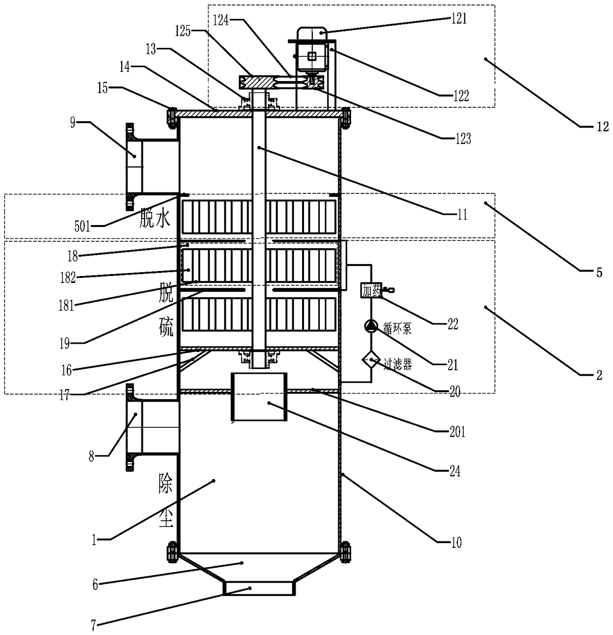
  • High-efficiency multi-stage rotary vane type dynamic liquid film treatment device and treatment method for flue gas
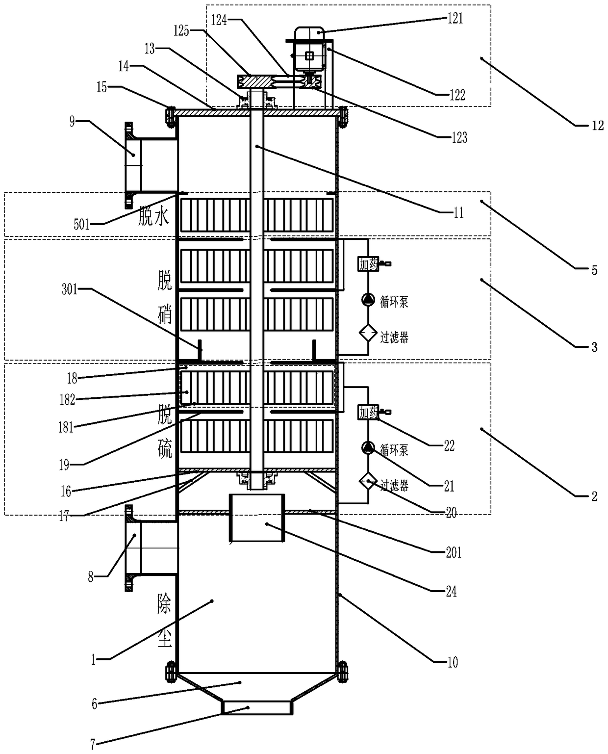
  • High-efficiency multi-stage rotary vane type dynamic liquid film treatment device and treatment method for flue gas
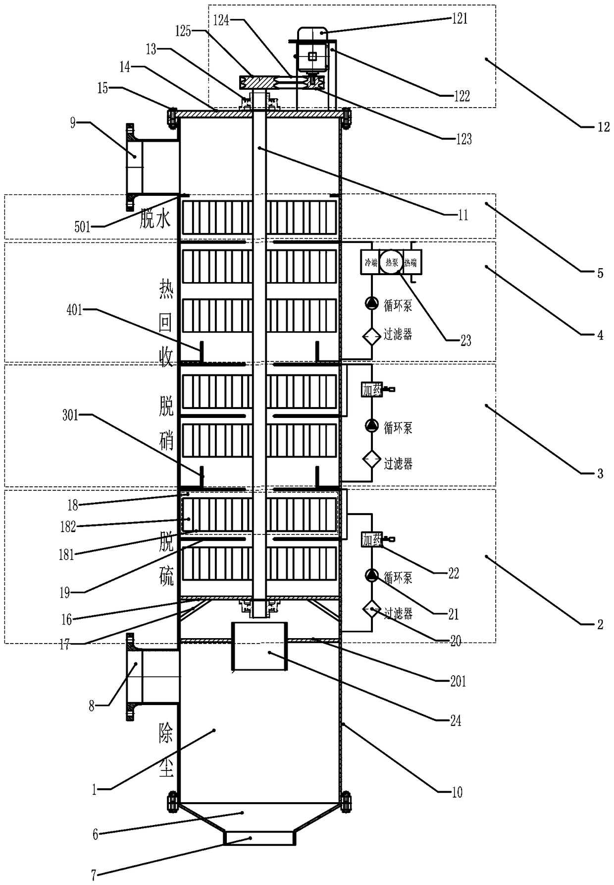
  • High-efficiency multi-stage rotary vane type dynamic liquid film treatment device and treatment method for flue gas

Examples


Embodiment 1

[0044] Embodiment 1, the high-efficiency multi-stage rotary vane type dynamic liquid film treatment flue gas device includes a cylindrical tower body (10) and a central rotating shaft (11), the top of the tower body (10) is provided with a cover plate (14), and the cover plate ( 14) It is fixed on the top of the tower body (10) through the flange (15), and the cover plate (14) is provided with a bearing seat (13) and a frequency conversion drive (12), and the frequency conversion drive (12) drives the central shaft (11) rotation; the variable frequency drive (12) consists of a variable frequency motor (121), a motor bracket (122), a motor V-belt pulley (123), a shaft V-belt pulley (125) and a V-belt (124), and the motor bracket ( 122) is fixed on the cover plate (14), the variable frequency motor (121) is fixed on the motor bracket (122), the shaft V-belt pulley (125) is connected with the central rotating shaft (11), and the motor V-belt pulley of the variable frequency motor ...

Embodiment 2

[0047] Embodiment 2, compared with Embodiment 1, a denitrification zone (3) is added, the denitrification zone (3) is set above the desulfurization zone (2), and there are at least two upper and lower levels in the denitrification zone (3). The same rotary vane device (18), each stage of the rotary vane device (18) in the denitrification zone (3) is also located on the central rotating shaft (11), and each stage of the rotary vane device (18) in the denitrification zone (3) ) and the inner wall of the tower body (10), there is a certain gap between the top of each stage of the rotary vane device (18) in the denitrification zone (3). The lower part of the leaf device (18) is provided with an annular denitrification water receiving tank (301) closely connected with the inner wall of the tower body (10), and the annular denitrification water receiving tank (301) is adjacent to the spray pipe (19 ), and above the spray pipe (19) of the desulfurization zone (2); the ring-shaped den...

Embodiment 3

[0049] Embodiment 3, compared with Embodiment 1 or Embodiment 2, a heat recovery zone (4) is added, the heat recovery zone (4) is set above the desulfurization zone (2) or the denitrification zone (3), and the heat recovery zone (4 ) is equipped with at least two stages of rotary vane devices (18) that are the same as those in Embodiment 1, and each stage of rotary vane devices (18) in the heat recovery zone (4) is also arranged on the central shaft (11). There is a certain gap between the outermost periphery of each stage of the rotary vane device (18) in the recovery area (4) and the inner wall of the tower body (10), and above each stage of the rotary vane device (18) in the heat recovery area (4). The spray pipe (19), the lower rotary vane device (18) of the heat recovery area (4) is provided with an annular heat exchange receiving tank (401) tightly connected to the inner wall of the tower, and the annular heat exchange receiving tank (401) is adjacent to the spray pipe (...


PUM


Abstract

The invention discloses a high-efficiency multi-stage rotary vane type dynamic liquid film treatment device and a treatment method for a flue gas. The treatment device for the flue gas comprises a cylindrical tower body and a central rotary shaft, wherein the central rotary shaft is penetratingly arranged in the center in a tower in a penetrating way; a cover plate is arranged at the top end of the tower body; a variable frequency drive device is arranged on the cover plate and drives the central rotary shaft to rotate; an inverted cone-shaped slagging area is arranged at the bottom end of thetower body; a dedusting area, a desulfurization area and a dewatering area are sequentially arranged in the tower body from bottom to top and communicate with one another; at least two stages of upper and lower rotary vane type devices are arranged in the desulfurization area; each stage of rotary vane type device in the desulfurization area is arranged on the central rotary shaft; at least one stage of rotary vane type device is arranged in the dewatering area; the dewatering area communicates with a flue gas outlet pipe. According to the treatment device for the flue gas provided by the invention, a dynamic liquid film is adopted, perpendicular sweeping, intense agitation, fresh liquid contact and multiple impact are applied, and the effective treatment time of the gas in the tower is long, so that the gas treatment efficiency is high; the gas can be treated thoroughly; the multifunctional integrated treatment is conveniently realized on the gas; the up-to-standard discharge is realized.

Description

technical field [0001] The invention belongs to the technical field of flue gas treatment, and in particular relates to an integrated device and treatment method for wet flue gas dust removal, desulfurization and denitrification. Background technique [0002] The treatment of gas pollutants is an important task in the current environmental protection work, typically the flue gas treatment of combustion devices, whether it is fuel oil, gas, coal-fired boilers or gas turbines, flue gas emitted by internal combustion engines, as well as food, medicine, For the discharge of polluting gases in industries such as chemical products, it is necessary to separate the pollutants in the gases and discharge clean gases into the atmosphere. In recent years, many new methods have emerged for gas treatment, mainly including dry method, semi-dry method, wet method, etc. The devices include fluidized bed, spray tower, bubbling bed, water bed, etc., with different principles and structures. T...

Claims


Application Information

Patent Timeline
Patent Type & Authority Applications(China)
IPC IPC(8): B01D53/75B01D53/78B01D53/50B01D53/56B01D53/48B01D47/00B01D45/12B01D50/00F28C1/00F28F25/02
CPCB01D45/12B01D47/00B01D53/48B01D53/50B01D53/56B01D53/75B01D53/78F28C1/00F28F25/02B01D2258/0283B01D50/40Y02P70/10
Inventor 陈坚陈闽钢
Owner 沈阳天航环保科技有限公司
Learn More