Single crystal silicon directional solidification seeding module
A directional solidification, single crystal silicon technology, applied in the direction of single crystal growth, single crystal growth, self-solidification method, etc., can solve the problem of difficult control of the temperature field of the single crystal silicon growth environment, achieve good fixed suspension effect, simple structure , the effect of convenient operation
- Summary
- Abstract
- Description
- Claims
- Application Information
AI Technical Summary
Problems solved by technology
Method used
Image
Examples
Embodiment 1
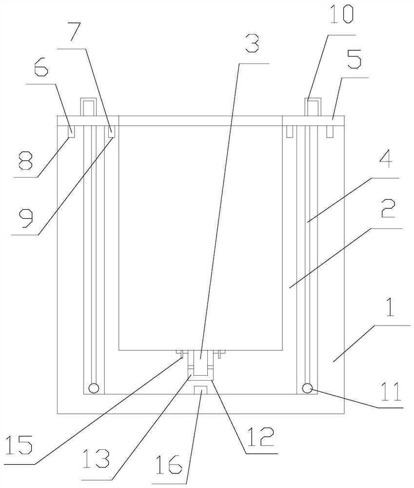
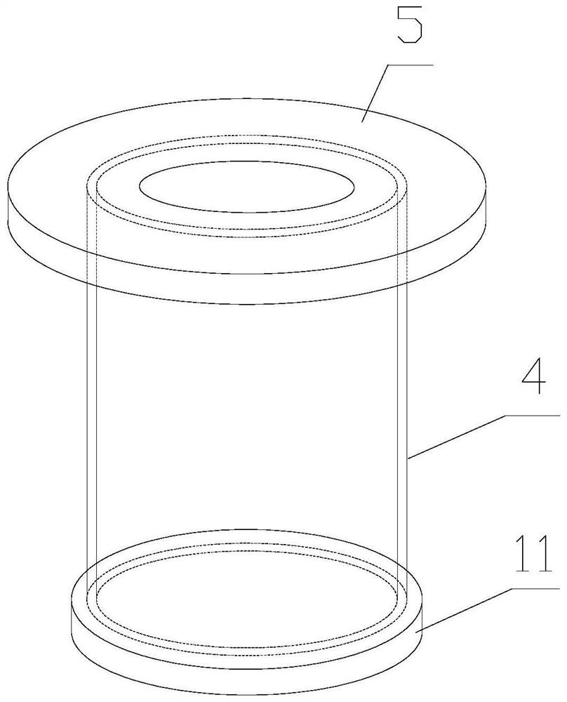
[0034] Single crystal silicon directional solidification seeding module, including a first crucible 1 and a second crucible 2, the second crucible 2 is sleeved in the first crucible 1, and an installation hole is opened at the geometric center of the inner bottom of the second crucible 2 12. A fixing member 13 for holding the seed crystal 3 is detachably connected in the installation hole 12; the outer diameter of the second crucible 2 is smaller than the inner diameter of the first crucible 1, between the first crucible 1 and the second crucible 2 Graphite thermal insulation woven sleeve 4 is arranged in the annular chamber between them, the graphite thermal insulation woven sleeve 4 has a cylindrical structure with both axial ends open, and the axial end of graphite thermal insulation woven sleeve 4 is fixed in the annular chamber by connecting piece The top end and the other axial end hang naturally on the bottom of the annular chamber under the action of gravity.
Embodiment 2
[0036]Further improvement on the basis of Example 1, the connector 5 is an annular plate structure, the inner diameter of the annular plate is equal to the inner diameter of the second crucible 2, and the outer diameter of the annular plate is equal to the outer diameter of the first crucible 1; graphite insulation One end open end of woven cover 4 is fixed on the lower plate surface of annular plate. A first positioning ring 6 and a second positioning ring 7 are also convexly provided on the lower plate surface of the annular plate along the circumferential direction; The first positioning groove 8 and the second positioning groove 9 adapted to the second positioning ring 7 are provided along the circumferential direction on the top end surface of the second crucible 2 . A lifting ring 10 is provided on the upper surface of the annular plate. A counterweight ring 11 is provided at the axial bottom end of the graphite thermal insulation woven sleeve 4; a positioning column 16...
Embodiment 3
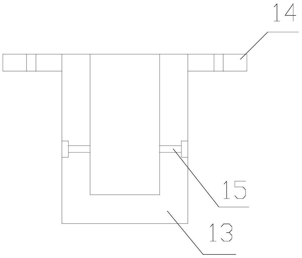
[0038] Further improvement on the basis of Example 2, the fixing member 13 is a cylindrical structure with one end open and one end closed, the seed crystal 3 is inserted into the cylindrical structure and fixed; the upper ring of the outer wall of the top open end of the cylindrical structure is provided with a limit plate 14, the limiting plate 14 is provided with a through hole, the bottom surface of the second crucible 2 and the outer edge of the mounting hole 12 is provided with a threaded hole adapted to the through hole, through the graphite pin 15 through the Through hole, screwed into the threaded hole to fix. The side wall of the cylindrical structure is provided with a threaded through hole, the axis of the threaded through hole is perpendicular to the axial direction of the cylindrical structure, and the seed crystal in the cylindrical structure is screwed into the threaded through hole by graphite pin 15. 3 Press and fix.
PUM
 Abstract
Description
Claims
Application Information
 - R&D
- Intellectual Property
- Life Sciences
- Materials
- Tech Scout
- Unparalleled Data Quality
- Higher Quality Content
- 60% Fewer Hallucinations
Browse by: Latest US Patents, China's latest patents, Technical Efficacy Thesaurus, Application Domain, Technology Topic, Popular Technical Reports.
© 2025 PatSnap. All rights reserved.Legal|Privacy policy|Modern Slavery Act Transparency Statement|Sitemap|About US| Contact US: help@patsnap.com


