Method for preparing C3N4 film

A C3N4, thin film technology, applied in the direction of electrodes, electrolytic coatings, electrophoretic plating, etc., can solve the problems of poor contact between the film and the conductive substrate, complex film preparation process, difficult to effectively control the film thickness, etc., to solve the problem of uncontrollable thickness, thin film The effect of controllable electrode thickness and simple and cheap preparation method

Inactive Publication Date: 2019-02-22
DALIAN MARITIME UNIVERSITY
View PDF1 Cites 4 Cited by
  • Summary
  • Abstract
  • Description
  • Claims
  • Application Information

AI Technical Summary

Problems solved by technology

But the C prepared by these methods 3 N 4 Thin films have different disadvantages, such as C 3 N 4 The contact between the film and the conductive substrate is poor, the film preparation process is complicated, and the film thickness is difficult to effectively control, etc.

Method used


Image

  • Method for preparing C3N4 film
  • Method for preparing C3N4 film
  • Method for preparing C3N4 film

Examples


Embodiment 1

[0028] This example illustrates an example of an electrophoretic deposition setup:

[0029] figure 1 For electrophoretic deposition of C 3 N 4 Schematic diagram of the apparatus used to prepare the films. Electrophoretic deposition is carried out in a two-electrode system, that is, both the working electrode and the counter electrode are conductive substrates, and the C 3 N 4 The precursor colloidal solution was ultrasonically homogeneous, and then the two electrodes were placed in C 3 N 4 Electrophoretic deposition is carried out by applying a DC voltage between the electrodes in the precursor colloidal solution.

Embodiment 2

[0031] This example illustrates C 3 N 4 Examples of precursor colloid preparation:

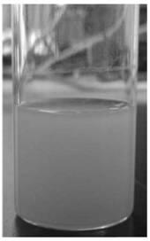
[0032] 2g C 3 N 4 Add 40mL of 98% concentrated sulfuric acid to the powder material and stir for 8 hours, then slowly add 200mL of aqueous solution and sonicate for 8 hours, centrifuge the precipitate on a 10,000-rpm centrifuge and wash it with water, then centrifuge, repeat 5-6 times until the centrifugation does not stop, and then centrifuge at 18,000 rpm get C 3 N 4 colloid, which was added to 120mL organic solvent, and ultrasonicated for 1 hour to obtain C 3 N 4 colloidal solution. Figure 2 shows the C 3 N 4 TEM images of colloidal particles and C 3 N 4 Photo of the colloidal solution, showing that the C prepared by this method 3 N 4 The size of the colloidal particles is about 20nm, and the particle size is uniform. In addition, the particles can be stably dispersed in organic solvents for a long time, which is suitable for the subsequent electrophoretic deposition process. ...

Embodiment 3

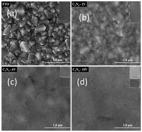
[0034] This example shows that by changing the electrophoretic deposition voltage to change C 3 N 4 Examples of control of thin film electrode thickness:

[0035] Put the precursor electrode prepared in Example 2 into the electrophoretic deposition reactor, use FTO conductive glass as the working motor and counter electrode of electrophoretic deposition, control the electrophoretic deposition time to 1min, and control the deposition voltage to 2V, 6V, and 10V for deposition, followed by natural drying at room temperature. image 3 The electron microscope image (SEM) shows the change of the surface morphology of the FTO substrate with the increase of the deposition voltage. It can be seen that the surface of the FTO conductive glass composed of rough particles is gradually covered by C 3 N 4 Covered with a thin film, the FTO substrate can be clearly seen at 2V, and the FTO substrate is basically covered by C at 6V. 3 N 4 Film coverage, the FTO substrate is completely cove...


PUM


Abstract

The invention relates to a method for preparing a C3N4 film by depositing C3N4 colloidal particles onto a conductive substrate through an electrophoresis method and conducting subsequent annealing treatment with C3N4 colloid highly dispersed in an organic solvent as a precursor and a conductive material as a substrate. Different from published methods for preparing C3N4 films, raw materials are cheap and easy to obtain, the film is flat, compact, uniform and controllable in thickness and makes contact with the substrate well, the preparation process is quick, and mass production is facilitated. The C3N4 film obtained through the preparation method can be used as a C3N4 photoelectrode for reactions such as photoelectrochemical decomposition of water for hydrogen production and photocatalytic degradation of organic substances, and can also be used for purposes such as surface protection and modification of materials.

Description

technical field [0001] The present invention relates to C in solar photoelectrochemical conversion process 3 N 4 The invention relates to a thin film preparation method, which belongs to the technical field of catalytic material preparation. Background technique [0002] Energy and environmental issues are becoming increasingly prominent in today's world, so countries around the world are actively developing and utilizing clean and sustainable energy technologies. Photoelectrochemical catalytic water splitting technology for hydrogen production can directly convert light energy into hydrogen energy, which is an important way of solar energy conversion. Fujishima and Honda discovered this phenomenon for the first time in 1972 (Nature 1972,238,37.), which caused a widespread research boom. Around this technology, people have developed various semiconductor materials for photocatalytic and electrocatalytic water splitting, such as TiO 2 (J. Am. Chem. Soc., 1983, 105, 27-31....

Claims


Application Information

Patent Timeline
Patent Type & Authority Applications(China)
IPC IPC(8): C25D13/02C25D13/22C25B1/04C25B11/06
CPCC25B1/04C25D13/02C25D13/22C25B11/051C25B11/075Y02E60/36
Inventor 杨波张轩豪刘伟白敏菂高宏何叶
Owner DALIAN MARITIME UNIVERSITY
Why Eureka
Try Eureka