High-efficiency voltage stabilization comprehensive control method of induction power transmission system

A technology of inductive power transmission and comprehensive control, applied in electrical components, circuit devices, etc., can solve problems such as affecting the quality of power transmission, voltage and current stress fluctuations of components, transmission power and efficiency decline, etc.

Active Publication Date: 2019-02-26
CHINA UNIV OF MINING & TECH
View PDF3 Cites 34 Cited by
  • Summary
  • Abstract
  • Description
  • Claims
  • Application Information

AI Technical Summary

Problems solved by technology

System parameters such as coupling coefficient, system frequency, and resonance parameters sometimes fluctuate greatly with the random relative position movement of the magnetic circuit mechanism. At the same time, the switching of loads will also greatly affect the quality of power transmission, causing transmission power and efficiency to decline. , voltage and current stress fluctuations of components, increase of strong electromagnetic interference, etc.

Method used


Image

  • High-efficiency voltage stabilization comprehensive control method of induction power transmission system
  • High-efficiency voltage stabilization comprehensive control method of induction power transmission system
  • High-efficiency voltage stabilization comprehensive control method of induction power transmission system

Examples


Embodiment 1

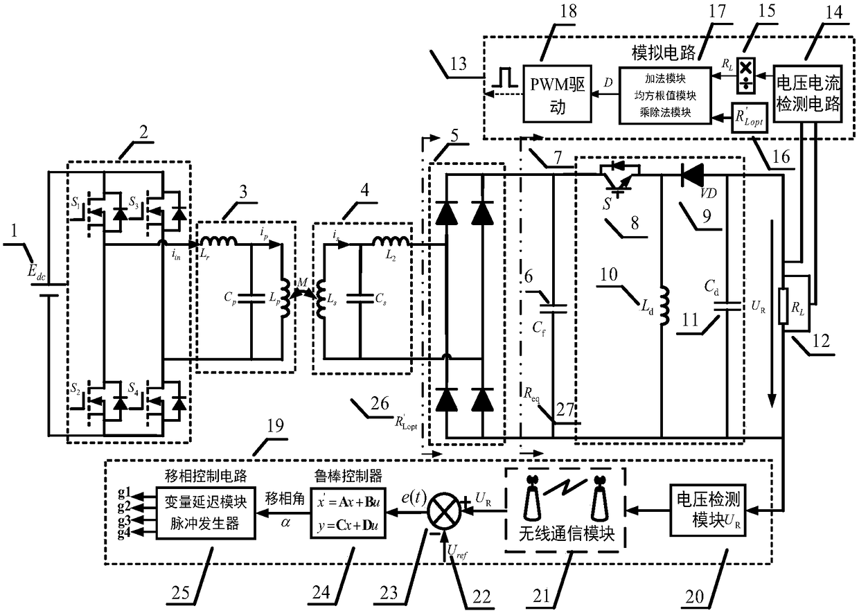
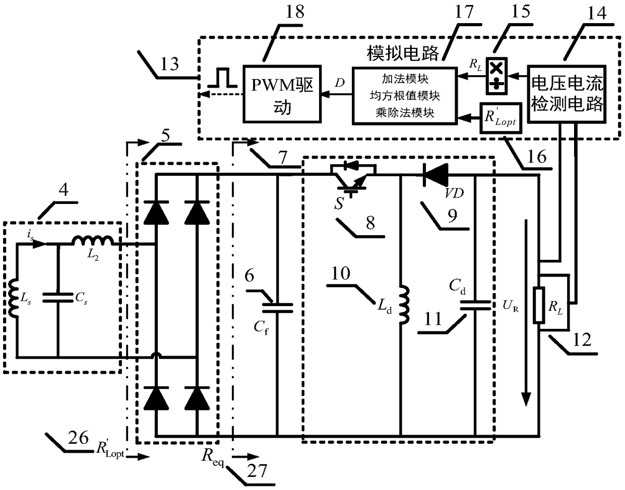
[0084] Embodiment 1: as figure 1 As shown, the inductive power transmission device of the present invention includes: DC voltage source 1, high frequency inverter 2, primary side LCL resonant network 3, secondary side LCL resonant network 4, rectifier circuit 5, filter capacitor 6 and BUCK-BOOST The converter 7 and the load 12; the DC voltage source 1 is connected to the input terminal of the high frequency inverter 2 to provide power for the high frequency inverter 2; the output terminal of the high frequency inverter 2 is input to the primary side LCL resonant network 3 The primary side LCL resonant network 3 is coupled with the secondary LCL resonant network 4, the output terminal of the secondary resonant network 4 is connected with the input terminal of the rectifier circuit 5, and the output terminal of the rectifier circuit 5 is connected with a filter capacitor 6 and BUCK-BOOST converter 7, the output end of BUCK-BOOST converter 7 is connected with load 12;

[0085] T...

Embodiment 2

[0110] Embodiment 2: as figure 1 As an inductive power transfer system with a working frequency of 85kHz, the input DC voltage E dc is 100V, the primary coil self-inductance L p and primary side resonant self-inductance L r The values ​​are the same, both are 35.059μH, the primary resonance capacitance is 0.1μF, the secondary coil inductance and secondary resonance inductance are both 35.059μH, the secondary resonance capacitance is 0.1μF, and the mutual inductance M is 12.271μH. Capacitance C f is 22μF, the inductor L in the DC-DC converter is 50μH, and the capacitor C L 50μF, coil internal resistance R p and R s Both are 0.2Ω, and the load is 30Ω. The process of its high-efficiency constant voltage comprehensive control is as follows:

[0111] According to the efficiency model of the circuit, the optimal load value under the optimal efficiency of the system can be obtained by differentiating the efficiency expression to the equivalent resistance:

[0112]

[0113] ...


PUM


Abstract

The invention relates to a high-efficiency voltage stabilization comprehensive control method of an induction power transmission system, belonging to the technical field of radio energy transmission.The system consists of two closed-loop circuits: an optimal efficiency tracking control loop and a robust constant pressure control loop. The optimal efficiency tracking control loop calculates the efficiency expression by establishing an AC impedance model for the system circuit, obtains the optimal equivalent load, adds an impedance matching network at a secondary side, and adjusts the duty cycle of a converter so that the equivalent resistance of the rectified output reaches the optimal load value to realize optimal efficiency tracking. The robust constant voltage control loop sends a difference between a load acquisition voltage and an input reference voltage into a robust controller by establishing a parameter perturbation model of the system to obtain a constant voltage of a high-frequency full-bridge inverter of a phase-shifted angle control primary side. The optimal efficiency tracking control and closed-loop robust control of an active impedance matching network can meet the multi-performance requirements of optimal efficiency and constant output voltage.

Description

technical field [0001] The invention relates to the technical field of wireless power transmission, in particular to a high-efficiency voltage stabilization comprehensive control system and method for an inductive power transmission system. Background technique [0002] The inductive power transfer technology uses the principle of electromagnetic coupling. The high-frequency inverter generates a high-frequency alternating magnetic field in space through the high-frequency alternating current generated by the primary coil, and the pickup coil induces a high-frequency alternating voltage in the high-frequency alternating magnetic field. In this way, the non-contact transmission of energy is realized by utilizing the spatial transfer of energy in the magnetic field. Compared with the traditional wire contact power supply mode, ICPT technology has the characteristics of safety, convenience, easy maintenance, and strong environmental adaptability, which can meet the needs of some...

Claims


Application Information

Patent Timeline
Patent Type & Authority Applications(China)
IPC IPC(8): H02J50/12
CPCH02J50/12
Inventor 夏晨阳孙琪琪李欣宇吴镇贾仁海吴远航路强
Owner CHINA UNIV OF MINING & TECH
Why Eureka
Try Eureka