Ballastless track structure

A ballastless track and track slab technology is applied in the direction of the track, the superstructure sub-assembly, the connection between the superstructure sub-assemblies, etc., which can solve the problems of difficult to transport materials, long construction period, poor vibration isolation performance, etc. To achieve the effect of easy handling and assembly, high work efficiency and long service life

Inactive Publication Date: 2019-03-01
张跃
View PDF6 Cites 3 Cited by
  • Summary
  • Abstract
  • Description
  • Claims
  • Application Information

AI Technical Summary

Problems solved by technology

[0003] However, the ballastless track is made of concrete and other materials, and still has the following defects: first, the construction period is long; second, it is difficult to transport materials, which is time-consuming and laborious; third, once damaged, it is not easy to repair; fourth, the vibration isolation performance is poor ; Fifth, the noise is loud

Method used


Image

  • Ballastless track structure
  • Ballastless track structure
  • Ballastless track structure

Examples


Embodiment 1

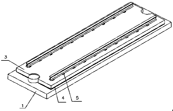
[0045] Such as figure 1 Shown: a ballastless track structure, including a foundation 1 and a track plate 3, both of which are spliced ​​by a plurality of metal plates 2, and the number of metal plates 2 depends on the overall length of the track. The track plate 3 is arranged on the foundation 1 , and the track plate 3 and the base 1 are connected by a flexible adhesive 4 . A fastening system 5 is provided on the track plate 2 .

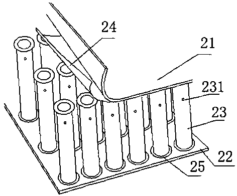
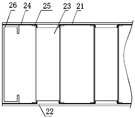
[0046] Such as figure 2 As shown: in this embodiment, the metal plate 2 includes a first panel 21, a second panel 22 and a plurality of hollow tubes 23 arranged between the first panel 21 and the second panel 22, the hollow tubes 23 and the first panel 21 1. A brazing layer is provided between the second panels 22; flanges 25 are provided at both ends of the hollow tube 23, and a circular structure is turned outward. The flanging 25 of the hollow tube is connected to the first panel 21 and the second panel 22 by soldering 24 .

[0047] Both the ...

Embodiment 2

[0053] On the basis of Example 1, all hollow tubes or part of the hollow tubes are filled with foaming materials through air holes, such as polyurethane stock solution, and foamed into foamed polyurethane in the hollow tubes; in addition, the hollow tubes can also be provided with foaming inorganic Particles, on the one hand, are convenient for rapid foaming when filled with polyurethane stock solution, and on the other hand, can improve the heat preservation effect. Filling the hollow tube with foam material not only plays a role of heat preservation, but also reduces the convection in the hollow tube and improves the sound insulation effect; moreover, the filled foam layer can be used as a supporting structure to prevent the hollow tube from bending and increase the The supporting force; and the foam has a long service life, because there is no air inside, cracks and various reactions will not occur.

Embodiment 3

[0055] Such as Figure 4 Shown: the difference with embodiment 1 is that brazing filler metal 24 ' punching flanging, and this flanging is to turn down vertically along the hole of brazing filler metal, so that hollow tube 23 is enclosed within the location on the flanging of brazing filler metal 24 '. The brazing material 24' is provided with a hollow 241' at the non-hollow tube place, so as to avoid the accumulation of the brazing material in the brazing process.

[0056] Other structures are with embodiment 1.


PUM


Abstract

A ballastless track structure includes a foundation and a track slab. The foundation and/or the track slab is made of metal plates; each metal plate comprises a first panel, a second panel and a plurality of hollow tubes arranged between the first panel and the second panel, and brazing layers are arranged between the hollow tubes and the first and second panels correspondingly; and at least one end of each hollow tube is provided with a flange. On the one hand, the ballastless track structure has the advantages of light dead weight, large strength, stable structure, high bearing capacity, sound insulation and noise reduction, high temperature resistance, vibration resistance, long service life, portability, assembly and the like; and on the other hand, the ballastless track structure canincrease the speed of rail vehicles such as high-speed trains and bullet trains.

Description

technical field [0001] The invention relates to the field of railway tracks, in particular to a ballastless track structure. Background technique [0002] Ballastless track refers to the track structure that uses concrete, asphalt mixture and other integral foundations to replace the loose-grained gravel track bed, also known as ballastless track, which is an advanced track technology in the world today. Compared with the ballasted track, the ballastless track can avoid ballast splashing, has good smoothness, good stability, long service life, good durability, less maintenance work, and the train running speed can reach more than 350km per hour. [0003] However, the ballastless track is made of concrete and other materials, and there are still the following defects: first, the construction period is long; second, it is not easy to transport materials, which is time-consuming and laborious; third, once damaged, it is not easy to repair; fourth, the vibration isolation perfor...

Claims


Application Information

Patent Timeline
Patent Type & Authority Applications(China)
IPC IPC(8): E01B1/00
CPCA45C5/02A45C5/045A45C5/14A45C13/001A45C13/04A45C13/36A47B13/08A47B96/02A47B96/206A47B2220/008A47C7/00B32B1/00B32B3/08B32B3/085B32B3/12B32B3/20B32B3/266B32B7/08B32B15/01B32B15/011B32B15/012B32B15/013B32B15/015B32B15/017B32B15/18B32B15/20B32B2250/40B32B2307/102B32B2307/304B32B2307/306B32B2307/3065B32B2307/50B32B2307/558B32B2307/714B32B2307/718B32B2419/00B32B2439/00B32B2479/00B32B2605/08B32B2605/10B32B2605/12B32B2605/18B62D25/00B62D27/02B62D29/00B63B3/26B63B3/48B63B3/56B64C1/12B64C2001/0081B65D81/3818B65D90/028E01B1/002E01B2204/09E01D19/02E01D19/083E01D19/125E01D2101/30E06B3/7015E06B2003/7049E21D9/14E21D11/155E21D11/18F16L9/21F16L59/02
Inventor 张跃
Owner 张跃
Why Eureka
Try Eureka