Lapping device capable of improving mandrel diameter difference and lapping method of lapping device

A lapping and mandrel technology, which is applied in the field of lapping devices to improve the diameter difference of mandrels, can solve the problems of large diameter differences of optical fiber preforms, uneven distribution of mandrel diameters, scrapped optical fiber preforms, etc., and achieve the improvement of wire drawing qualification rate, optimize diameter uniformity, and improve the effect of diameter uniformity

Pending Publication Date: 2019-03-08
JIANGSU TONGDING OPTICAL WAND
View PDF3 Cites 0 Cited by
  • Summary
  • Abstract
  • Description
  • Claims
  • Application Information

AI Technical Summary

Problems solved by technology

The OVD deposition seed rod is composed of a mandrel and a handle rod. After deposition and sintering, the rod becomes an invalid part. At present, the length of the seed rod required by OVD deposition equipment is fixed. If the length of the core rod is insufficient, the length of the handle rod can only be extended. But this will lead to more waste of OVD cladding
The length of the OVD deposition mandrel can be effectively increased by using the mandrel butt joint process, but due to the butt joint of the mandrels, the diameter of the interface is quite different, which makes the diameter distribution of the whole mandrel after butt jointing uneven, resulting in prefabricated optical fibers manufactured after OVD deposition and sintering. There is a large difference in the diameter of the rod, and the proportion of scrapped optical fiber preforms due to large fluctuations in the diameter of the optical fiber during the drawing process is relatively high
In addition, due to the large residual stress when the mandrel is butted, it will also lead to a large proportion of mandrel cracking
Therefore, there is an urgent need for a low-loss optical fiber rod core rod interface, which can effectively avoid the problems of large fluctuations in the diameter of the optical fiber due to the presence of air bubbles, impurities, and voids in the uneven diameter of the optical fiber preform during the extension process, and the problems of fiber breakage and coating glue leakage. , device and method for improving optical fiber strength and drawing efficiency

Method used


Image

  • Lapping device capable of improving mandrel diameter difference and lapping method of lapping device
  • Lapping device capable of improving mandrel diameter difference and lapping method of lapping device
  • Lapping device capable of improving mandrel diameter difference and lapping method of lapping device

Examples


specific Embodiment 1

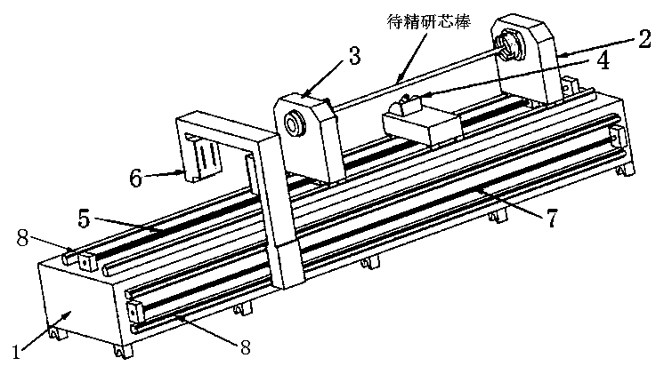
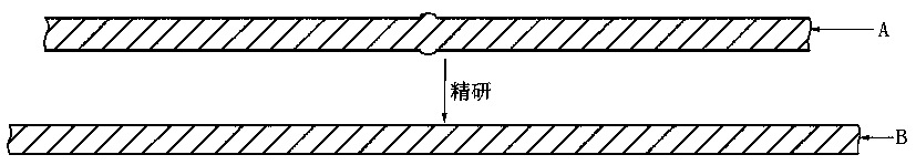
[0033] Specific embodiment 1: Carry out lapping on mandrels of up to standard length with wrinkled appearance or other defects and mandrels of up to standard length with uneven diameters. Such as figure 2 As shown, firstly carry out PK test on mandrel A with wrinkled appearance or other defects or non-uniform diameter and reach the standard length, then degrease, clean, dry, anneal and remove residual stress to obtain the mandrel to be lapped, and then fix it by The movable jaws of chuck 2 and sliding chuck 3 fasten the rods at both ends of mandrel A to be lapped, turn on the start switch, and the fixed chuck 2, sliding chuck 3, blowtorch 4 and diameter scanner on the lapping device 6 is electrically connected to the controller, click the "Start" button on the controller, the controller drives the diameter scanner 6 to move along the second drive screw 7 and the boss slideway 8 on the side bed surface of the lapping machine 1 to measure the The diameter of the mandrel A is l...

specific Embodiment 2

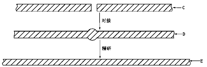
[0034] Specific embodiment 2: butt jointing and lapping of mandrels with insufficient segment lengths and uneven joint diameters. Such as image 3 As shown, the two mandrels C with insufficient segment length are firstly subjected to the mandrel PK test, followed by degreasing, cleaning, drying, annealing and residual stress removal treatment, and then the two mandrels C with insufficient segment length after the above treatment Fix on the fixed chuck 2 and sliding chuck 3 respectively, turn on the start switch, the fixed chuck 2, sliding chuck 3, blowtorch 4 and diameter scanner 6 on the lapping device are electrically connected to the controller, click on the controller Press the "Start" button on the button, the controller drives the blowtorch 4 to slide along the first transmission screw 5 and the boss slideway 8 on the upper surface of the lapping machine 1 to the docking ends of the two mandrels C with insufficient length, and manually ignites the blowtorch 4 Heat the t...


PUM


Abstract

The invention discloses a lapping device capable of improving mandrel diameter difference. A fixed chuck and a sliding chuck are respectively mounted on the upper lathe surface of a lapping machine tool; a torch lamp is further arranged on the upper lathe surface of the lapping machine tool; the torch lamp is arranged between the fixed chuck and the sliding chuck; a first transmission lead screw is further arranged on the upper lathe surface of the lapping machine tool; a diameter scanner is arranged on the side lathe surface of the lapping machine tool; the diameter scanner is 7-shaped; the upper part of the diameter scanner stretches over the upper lathe surface of the lapping machine tool; a second transmission lead screw is further arranged on the side lathe surface of the lapping machine tool; the fixed chuck, the sliding chuck, the torch lamp and the diameter scanner are all externally connected with a controller; and the controller controls and drives the fixed chuck, the sliding chuck and the torch lamp to move correspondingly along the first transmission lead screw, and controls and drives the diameter scanner to move correspondingly along the second transmission lead screw, so that mandrel butt-joint and lapping are realized, and therefore, mandrel diameter uniformity is effectively improved; a mandrel utilization rate and a wire-drawing qualification rate are increased; and meanwhile, the total length of the mandrel is enabled to reach the standards, and waste of raw materials is reduced.

Description

technical field [0001] The invention belongs to the technical field of optical fiber prefabricated rod production, and in particular relates to a lapping device and a lapping method for improving the diameter difference of core rods. Background technique [0002] Large-size optical fiber preform has the advantages of long effective length, large diameter, and effective drawing length exceeding 2000KM. It is the core of the optical fiber industry to reduce production costs and improve product competitiveness. OVD deposition process, because the doping has been completed in the manufacturing process of the core rod (with a small amount of outer cladding), so the requirements for the raw material of the outer cladding are lower than that of the core rod, the process is easy to control, the production efficiency is high, and it is very easy to manufacture large-scale optical fiber prefabrication Great. The OVD deposition seed rod is composed of a mandrel and a handle rod. After...

Claims


Application Information

Patent Timeline
Patent Type & Authority Applications(China)
IPC IPC(8): C03B37/018
CPCC03B37/018
Inventor 沈小平崔德运何炳谈悠儒杨意马逸聪蒋锡华朱坤满小忠
Owner JIANGSU TONGDING OPTICAL WAND
Why Eureka
Try Eureka